Issue/Rev. 0.5 (6/11)
MN01029 • Page 15
Section 3 – Meter Repairs
Replacing Adjusting Stem Assembly
The adjusting stem assembly may be replaced as a unit
or it may be disassembled and repaired. If disassembly
ofadjustingstemisdesired,refertoSmithPartsList
for part numbers of replaceable items. See Page 21 for
applicablePartsListNo.foreachmetertype.
Toreplaceassembly:
1. Remove knob cover.
2. Unscrew the two screws securing adjusting stem
assembly to meter cover and remove assembly,
Figure 53.
•Noteadjustingstemadapter.Besurethisadapter
is in position when new or repaired adjusting stem
assembly is installed.
Replacing Packing Gland
Note: Meter must be drained and all pressure relieved
before beginning this procedure.
The packing gland may be replaced without having to
removethemetercover.Toreplacepackinggland:
1. Remove all accessories and calibrator from top of
meter.
2. Remove cotter pin and drive washer, Figure 54.
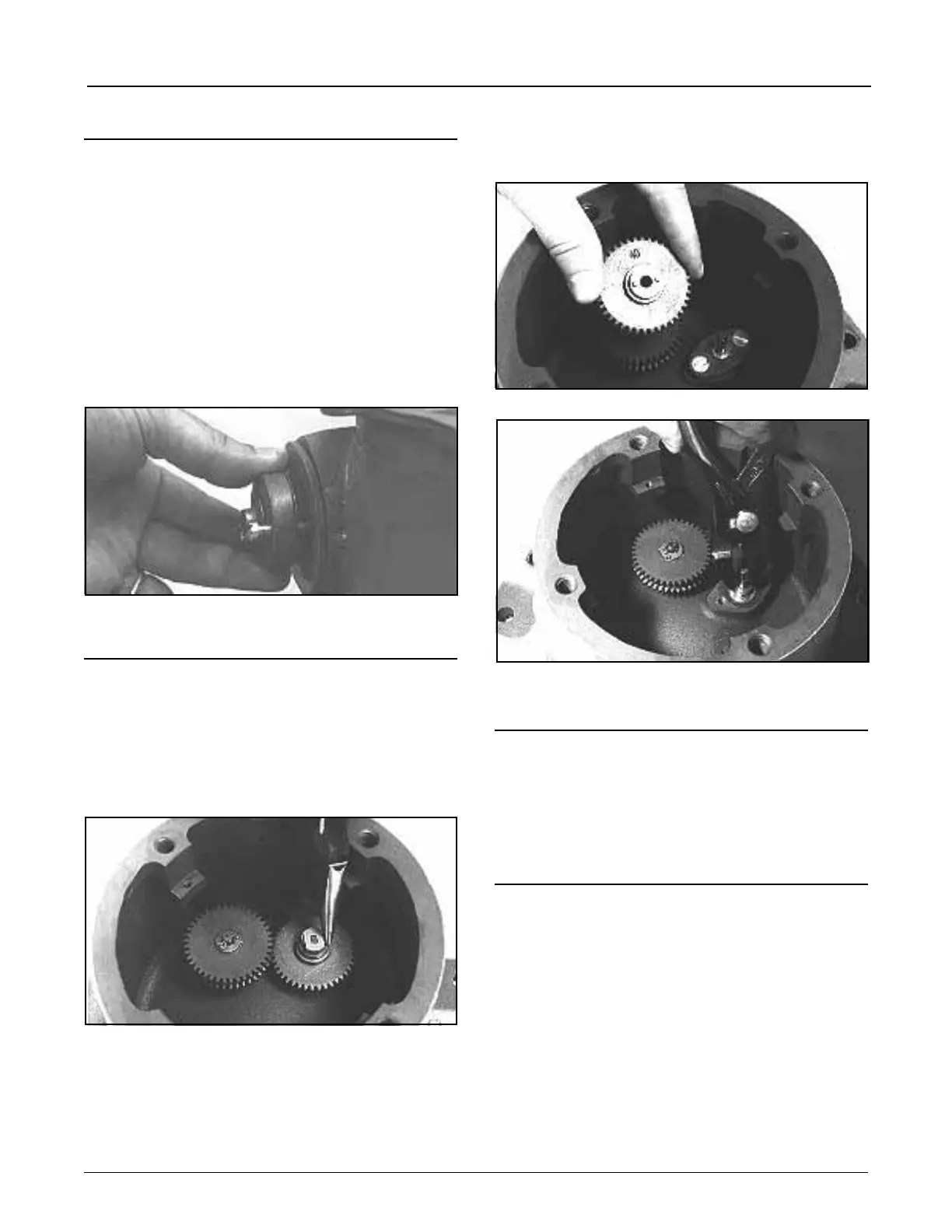
3.Liftsinglepiniongearfromjackshaft,Figure55,and
remove packing gland flange.
4.Liftpackingglandfromcover,Figure56.
•Ifpackingglandisdifculttoremovewiththengers,
use a pair of pliers as shown in Figure 56.
5. Install new packing gland and reassembled items
removed in Steps 1, 2, and 3.
•Replacepackingglandgasket,Figure56,ifrequired.
Figure 55
Installing New Rotor
Should it become necessary to replace a rotor assembly,
refer to the Clearance Checks Section of this manual
and perform all necessary checks to fit new rotor into
housing. After rotor is fitted to housing, refer to Adjusting
Rotor End Clearances, Page 9.
Replacing Blade Assembly
1. Install appropriate spider (see Suggested Tools and
Fixtures, Page 2) and perform clearance checks as
outlined in Clearance Check Section of this manual.
2. In most instances, clearances with new blades will
befoundtobetooclose.Whenthisisthecase,the
complete rotor assembly must be removed and the
blade ends dressed down.
•Figure 57 shows the proper manner in which to
accomplish this filing operation. Use a vise with soft
jaws or otherwise properly protect the blade held
by the vise.
•A Vixen (babbit metal) le is recommended for
aluminum blades. A mill coarse file should be used
on cast iron blades.
Figure 54
Figure 56
Figure 53