Page 2 • MN01029 Issue/Rev. 0.5 (6/11)
Section 1 – General Information and Description
It is suggested that a detailed record be maintained
for each meter. Nameplate data, clearances, progres-
sive totalizer readings, meter factor, parts used, and
other similar information provide background material
for scheduling a preventive maintenance program. An
increase in meter factor drift against throughput can be
used as the basis for making an inspection.
The time of the first inspection must be based on the
operating conditions imposed by the installation. Flow
rate, lubrication properties of the fluid, and the possibility
of abrasive contaminants are points to consider. Then,
at the time of inspection, the condition of the meter
should indicate whether the inspection interval can be
lengthened or shortened.
All parts, as they are removed, should be thoroughly
washed and cleaned in solvent. Parts that are worn
enough to affect operation or calibration should be re-
placed. All parts that are nicked, gouged, or have rough
places on them, should be dressed with a fine file or
crocus cloth, as conditions warrant.
Before any disassembly is performed on the meter, be
sure that the trouble is in the meter.
1. Check that meter is being operated within the proper
flow rate. Refer to the nameplate on the side of the
meter.
2. If rotor does not turn freely, adjust end clearance. See
Adjusting Rotor End Clearances, Page 9.
3. Check calibrator for proper operation.
4. Check air eliminator and strainer assembly.
5. Check valve operation.
After all other accessories have been checked and found
to be operating normally, the meter should be checked.
Description
Smith Meter
®
single-case rotary meters are of the posi-
tive displacement type. The metering mechanism is a
rotor assembly set in the housing. Pipe connections are
confined to the housing, which means the rotor assem-
bly can be removed by taking off the cover assembly and
lifting the rotor assembly out. Inspection, maintenance,
and service is greatly simplified.
The measuring function is accomplished in a chamber
of precise volume created by the moving blades, rotor,
housing, and cover. There is a smooth flow of product
through the meter. The blades rotate around a fixed
cam which causes them to move out to, but not touch,
the body of the meter. Four chambers per revolution are
formed as the rotor and blades are turned by product
flow.
FMC Technologies Measurement Solutions, Inc. pro-
vides a meter variation with tungsten carbide trim to
resist the accelerated wear that can be caused by im-
1-1/2"
3/4"
3/4"
9"
9"
2" Dia.
Figure 1
Figure 1A
purities such as sand and iron sulfide and also by the
low lubricity of condensates. This variation uses solid
tungsten carbide journal rotor and thrust bearings. In
addition, blade bearings’ size and weight have been
reduced to minimize the rotational inertia of the cam
followers and the wear resistance of the bearings and
cam have been substantially increased. Also, the rotor
and jackshaft gear assemblies have been changed to
hardened stainless steel.
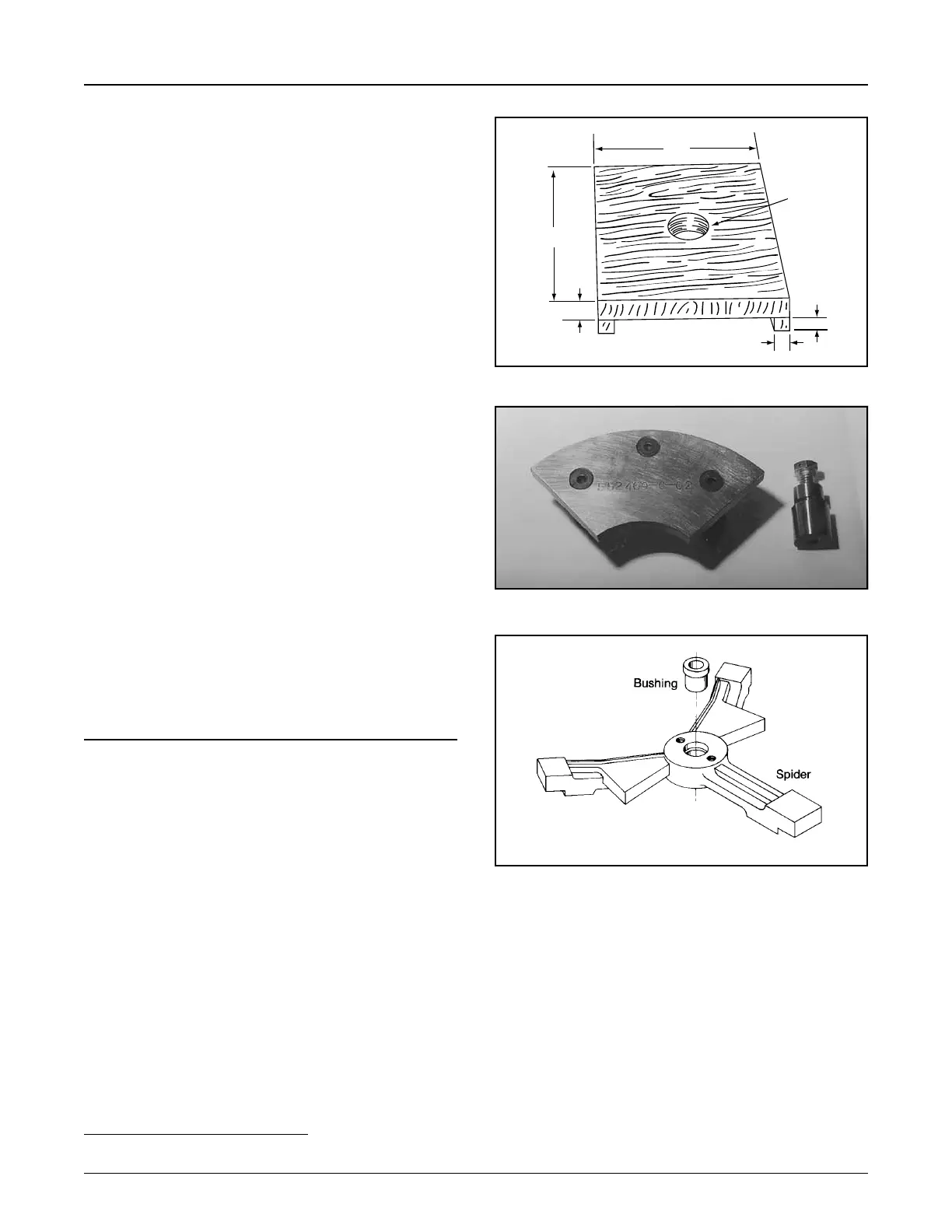
Figure 2 — Spider and Bushing
1 Consists of feeler gauge soldered to 15" rod. An extension rod (22") and coupling is available as Part Number 515250.