Issue/Rev. 0.5 (6/11)
MN01029 • Page 11
3. RemovetheAdjustingScrew.CleanandapplyLOC-
TITE242.Figure40indicateswheretheLOCTITEis
to be applied.
4. Figure 41 is a photo of the locking mechanism.
SCREW(TOP),ADJUSTINGCAP(MIDDLE)(NOTE:
the arrows point to a gasket at the base of the Adjust-
ing Cap and a brass gasket in the top of the Adjusting
Cap. These gaskets need to be in place to create a
leakproofseal.),ANDADJUSTINGSCREW(BOT-
TOM).AftertheAdjustingScrewhastheLOCTITE
applied install it into the meter cover. Install the Ad-
justing Screw until it bottoms out. Install the Adjusting
Cap on the Adjusting Screw.
Section 1 – General Information and Description (continued)
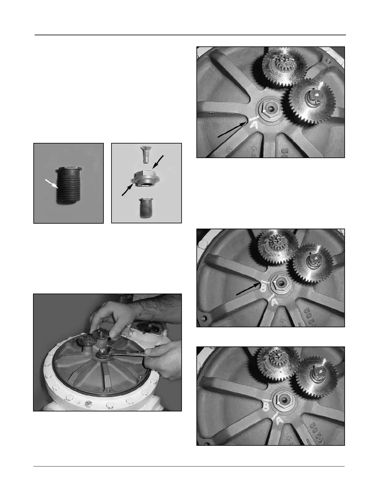
5. Use a 3/4” wrench to turn the Adjusting Cap and Ad-
justing Screw clockwise (Figure 42). Apply torque to
the Jack Shaft Gear while turning the Adjusting Cap
and Adjusting Screw clockwise. The Jack Shaft Gear
willbegintospinastherotorheightisadjusted.When
the rotor begins to spin mark a line and label the line
“A” (Figure 43). The rotor is now in the up position.
Figure 40
Figure 41
6. Continue to apply torque to the Jack Shaft gear while
turning the Adjusting Cap. The rotor will begin to drag.
Whentherotorbeginstodragstopturningthead-
justment cap and put a line and label the line “B” as
Figure 42
illustrated in Figure 44. The rotor is now in the down
position. Rotate the Adjusting Cap counter clockwise
until the line on the Adjusting Cap is approximately
1/3 of the distance from the line “A” as illustrated in
Figure 45. Turn the Jack Shaft gear and check for the
rotor to spin free. The Adjusting Cap may need to be
adjusted slightly to ensure the rotor spins freely.
Figure 43
Figure 44
Figure 45