Page 10 • MN01029 Issue/Rev. 0.5 (6/11)
Section 1 – General Information and Description (continued)
Figure 35
3.With rotor revolving, turn Allen wrench clockwise
slowly until rotor again meets resistance, Figure 35.
4. Rotor is now in the full down position. Mark this posi-
tion (Point C) on hub, Figure 35.
5. Turn Allen wrench counterclockwise until Points A
and B are realigned as in Figure 35.
6. Now turn Allen wrench clockwise until Point B (on
Allen wrench) is 1/3 distance from Point A, Figure 36.
•Rotorshouldnowrotatefreely. If not, recheckall
clearances.
7. Reinstall gasket and access plug in bottom of housing.
•Checkgasketfordamage.Replaceifnecessary.
Figure 36
Procedure for Rotor End Adjustment and
Application of Loctite
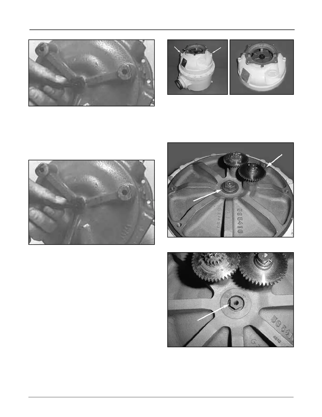
The following procedure applies to the ASD-3V-NF.
1. Figure 37 shows the meter in an assembled state. The
arrows point to two 5/16" bolts. Remove these two
5/16"boltsusinga1/2”wrench.Whentheboltsare
removed the meter adapter can be removed (Figure
37A) allowing access to the rotor adjustment screw.
Figure 37
2. Figure 38 illustrates the meter with the adapter re-
moved. The arrow points to the locking mechanism
for the rotor end adjustment and the Jack Shaft gear.
Figure 39 shows the Adjusting Screw with the Adjust-
ing Cap and Screw removed.
Figure 38
Figure 39
Figure 37A