Page 8 • MN01029 Issue/Rev. 0.5 (6/11)
next level assemblies (rotor gear plate or rotor
subassembly) be procured with bearings already
installed, or capabilities must permit epoxying
bearings in precise alignment.
6. The blades are matched to their own slots. Therefore,
before removing blades from the rotor, the blades and
rotor slots must be matched-marked.
•Figure26showsonemethodofmarkingbladeand
rotor. Using a marker, make identical notches (in
this case, two) on the back end of the blade and on
rotor area next to blade slot. It is unnecessary to
mark opposite paddle of blade for obvious reasons.
7. The lower blade assembly can now be removed.
•Because of the position of the rollers, it will be
necessary to maneuver the blade assembly out of
the rotor.
•Handlebladecarefullysothatedgesofbladesare
not damaged.
•Ifrollersrequirereplacement,refertoPage12for
replacement procedure.
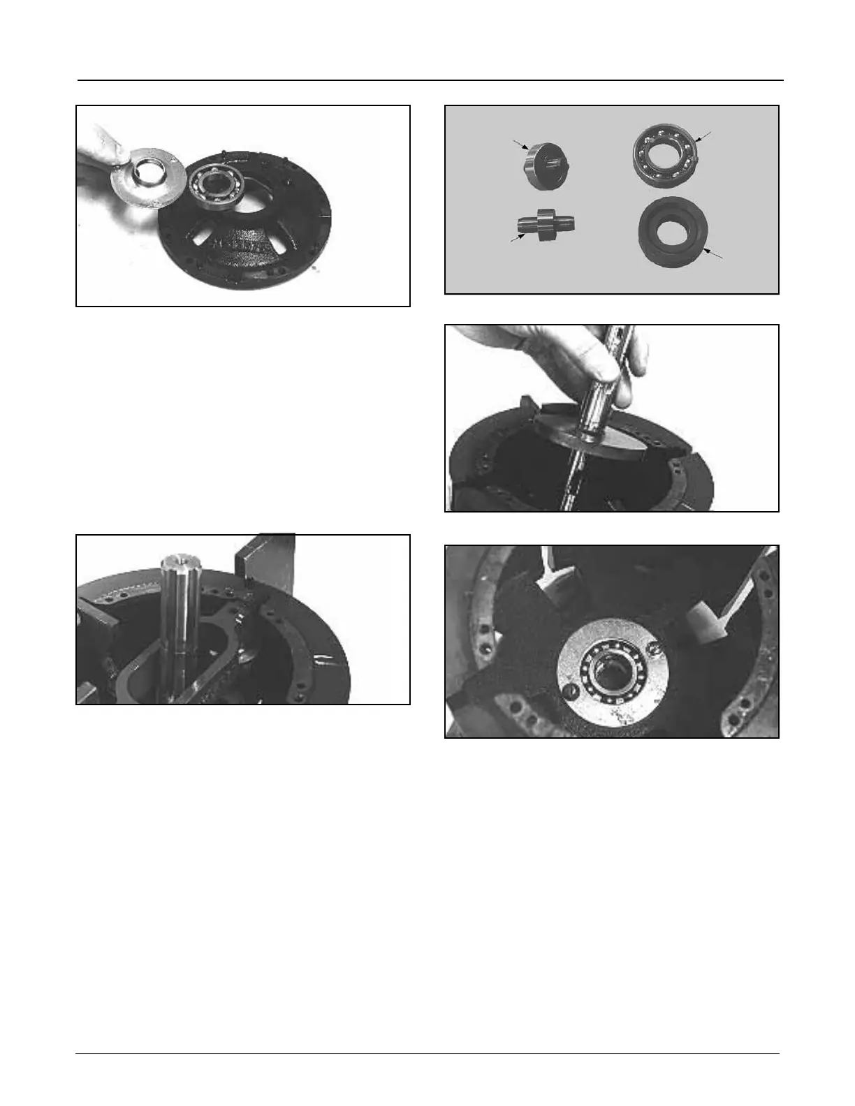
•SeeFigure27foralternatebladeandrotorbearings.
8. The cam and shaft assembly is lifted out of the rotor,
Figure 28.
•Thecamissecuredtotheshaftbyakey,Figure28.
Figure 25
Standard Blade
Bearing and Pin
Tungsten Carbide
Blade Bearing
and Pin
Standard Rotor
Bearing
Tungsten
Carbide
Rotor
Bearing
Figure 27
Section 1 – General Information and Description (continued)
Figure 26
Figure 28
Figure 29
9. Mark upper blade assembly and rotor and remove
blade assembly.
•Usedifferentsetofmarksthanusedonlowerblade.
•Notebearingkeyonrotorbearing,Figure29.This
key is not bonded to the bearing and may fall off
after shaft is removed. Be sure this key is in place
when shaft is reinstalled. An application of vasoline
will aid in keeping the key in position.
10. Remove clamping ring, Figure 29, and rotor bearing.