Issue/Rev. 0.5 (6/11)
MN01029 • Page 7
4.Whenrotorassemblyisremovedfromthehousing,
turn it upside down and place it on a wooden block
or metal plate.
•Thewoodenblockorplatemusthaveaclearance
hole in the center for the shaft and must be high
enough to allow the shaft to clear the table. See Fig-
ure 1 for dimensions in constructing a wooden block.
•Ifrotorassemblyistobesetasidetemporarily,it
may be laid on its side. However, cardboard or other
suitable cushion should be placed under it to protect
the blades from damage.
5. The block, Figure 19, can be separated from the
housing by removing the two bolts in the side of the
housing.
•When replacing the block, a sealant must be
appliedtothetwoblockretainingbolts(Master
Gasket by Loctite is recommended).This will
preventleakage.
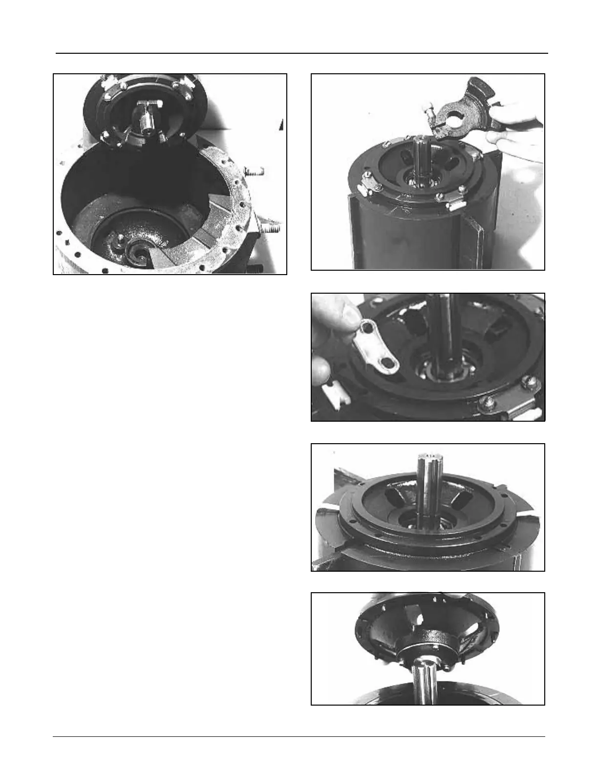
Rotor Disassembly
1. Using an Allen wrench, loosen locating arm screw
and pull locating arm from shaft, Figure 21.
2. Remove key and retaining ring from shaft, Figure 21.
3. Remove clamps and blade blocks, Figure 22, from
assembly.
4. Using two screwdrivers, pry off rotor cover, Figure 23.
• Slots are provided in the cover to accept the
screwdriver blades. Place screwdrivers opposite
each other and pry upward uniformly. Do not pry
downwardwithscrewdrivers,asdamagecould
occur to the top edge of the rotor body.
•Notelocatingpinsincover,Figure24.
5. The rotor cover consists of the cover, Marcel ring,
rotor bearing, and lower bearing shield, Figure 25. If
replacement of tungsten carbide outer radial bear-
ings is necessary, it is recommended that complete
Figure 20
Figure 21
Figure 22
Figure 23
Figure 24
Section 1 – General Information and Description (continued)