Before installing the main wing, horizontal tail and vertical
tail, the linkage rods for ailerons, flaps, elevators and
rudder should be installed in advance. Make sure the servos
are in neutral position. Attach the “Z” bend end of aileron,
flap, elevator and rudder linkage rods to the corresponding
holes in the aileron, flap, elevator and rudder control arms
from the outside as shown (Please refer to the control horn
and servo arm settings and clevis installation sections in
manual ). And then install the ball buckleat the other end of
the linkage rods to ball head at each control horn on control
surfaces.
10
EN
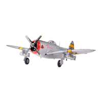
Control horn and servo arm settings
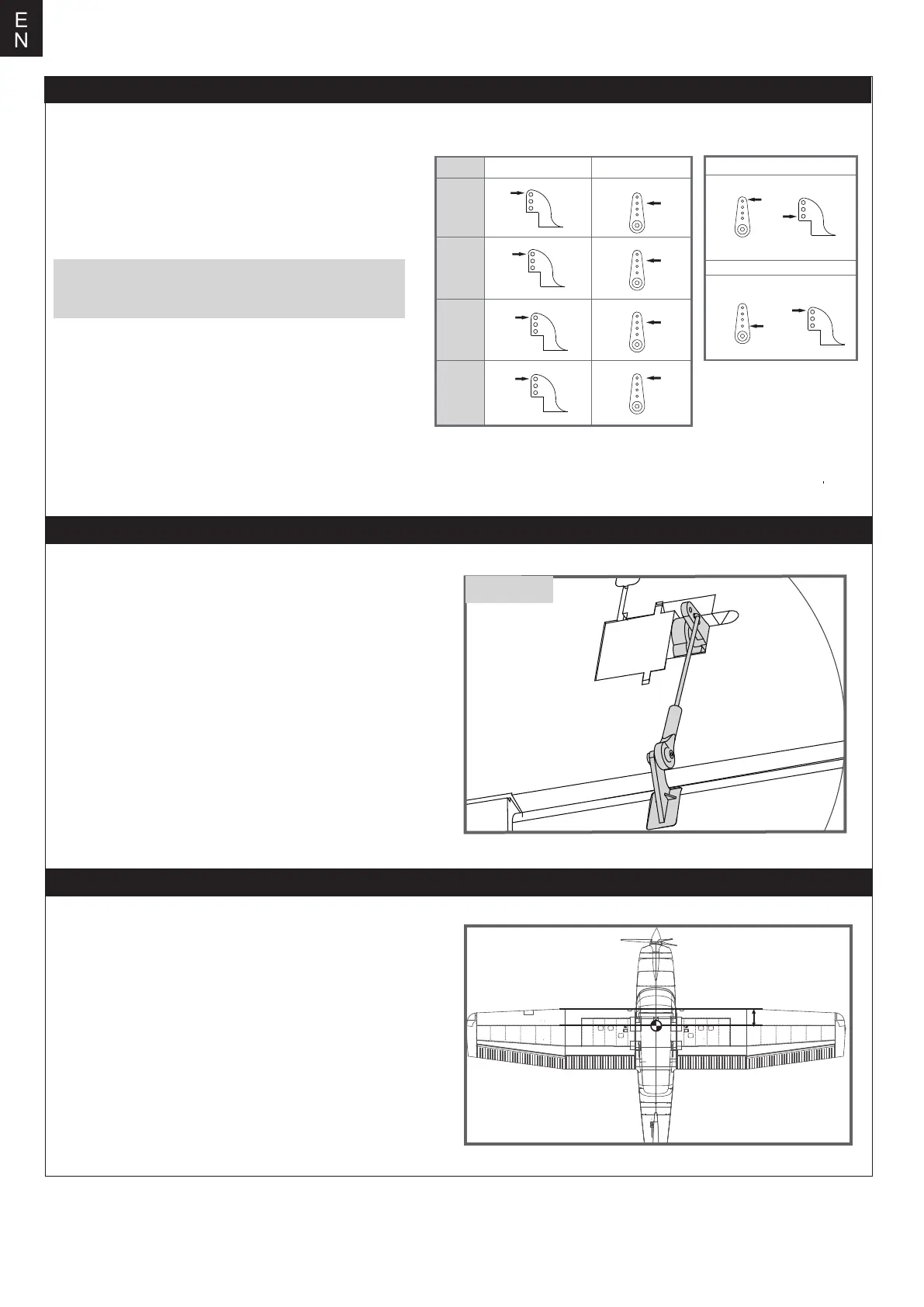
Check the C.G. (Center of gravity)
Linkage rods installation
ball head
When balancing your model, adjust the battery as neces-
sary so the model is level or slightly nose down. This is the
correct balance point for your model. After the first flight,
the CG position can be adjusted for your personal prefer-
ence.
1. The recommended Center of Gravity (CG) location for
your model is(55-65mm) from the leading edge of the main
wing (as shown) with the battery pack installed. Mark the
location of the CG on top of the wing.
2. When balancing your model, support the plane at the
marks made on the bottom of the main wing with your
fingers or a commercially available balancing stand. This is
the correct balance point for your model. Make sure the
model is assembled and ready for flight before balancing.
More control throw
Less control throw
Horns Arms
ElevatorRudderAilerons
Flaps
55mm-65mm
The table shows the factory settings for the control
horns and servo arms. Fly the aircraft at the factory
settings before making changes.
After flying, you may choose to adjust the linkage
positions for the desired control response.
Note: Do not increase the flap angle or the flap travel
of the remote control to prevent the servo from being
blocked and burned.