10 Handler I, II & III Operator’s Manual - October 2008
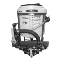
Step 2
Venturi package assembly
Figure H1-4.3
Thread venturi assembly to anti-vortex fitting on tank bot-
tom. Be sure to use sealant as per instructions.
NOTE: the discharge end of the venturi once installed
should point to the left hand side behind tabs. (See Fig.
H1-4.3)
Step 3
Bracket installation
Figure H1-4.4
Install venturi bracket to tabs on the Handler frame as
shown in Fig. H1-4.4 using ¼” x 1” bolts. Do not tighten
completely yet.
Install smaller ball valve support bracket on to venturi
bracket using 5/16” x ¾” bolts. Do not tighten completely
yet. (See Fig. H1-4.4)
1.
•
2.
3.
Figure H1-4.5
Attach bypass valve assembly to venturi assembly using
stainless steel flange clamp (25-FC200) and gasket (25-
150G) making sure that the 2” ball valve (10-10230) sits on
the support bracket. Do not tighten clamp completely yet.
(See Fig. H1-4.5)
Step 4
Bypass valve installation
Fasten 2” ball valve to support bracket using 5/16” x ¾”
bolts, 3/8 flat and 5/16 lock washer.
Tighten all bolts and clamps.
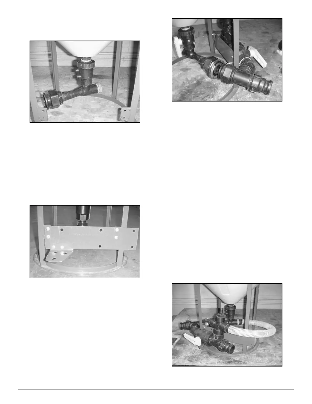
Step 5
Hose and clamp installation
Thread female end of hose barb on venturi hose assembly
on the intake side of the venturi (86-HV150).
Note: Use Sealant on both male and female threads.
Important: Make sure venturi nozzle is in place before
installing venturi hose.
Figure H1-4.6
4.
1.
2.
1.
•