14 Handler I, II & III Operator’s Manual - October 2008
Handler II Assembly
Overview
Assembly of your Handler 2 (without pump) follows four basic
steps:
Rinse valve and agitation fitting assembly and installation.
Venturi bracket and plate installation.
Three way valve support bracket installation
Venturi package assembly and installation.
If you have purchased a Handler 2 with a pump or recirculation
package then there are two additional Steps:
Pump bracket installation.
Pump and recirculation package installation.
Step 1
Rinse valve and agitation fitting assembly
and installation
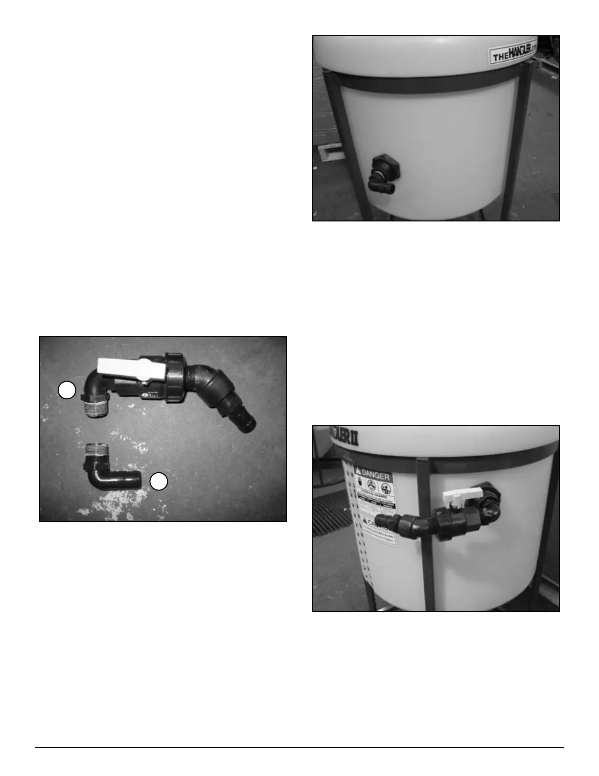
FIgure H2-4.1
Agitation Fitting Installation (Figure H2-4.1, “A”).
Install 1” MPT X 1” HB 90 (25-HB100-90) on to 1” bulk-
head on left side of tank. See figure H2-4.2. (Apply sealant
before assembling - see notes on page 37)
1.
2.
3.
4.
1.
2.
1.
Figure H2-4.2
Rinse Valve Assembly (Figure H2-4.1, “B”)
Install one 1” MPT X 1” MPT elbow (10-10980) on to 1”
single union ball valve (25-UV100FP) on end opposite of
union. (Apply sealant before assembling - see notes on
page 37)
Install 1” MPT X 1” Hose Barb (25-HB100) onto end of
street elbow.
Install 1” street elbow 45 degree (25-SL100-45) into union
side of ball valve.
Attach the above assembly to 1” bulkhead on right side of
tank (see figure H2-4.3).
Figure H2-4.3
1.
2.
3.
4.
A
B