12 Handler I, II & III Operator’s Manual - October 2008
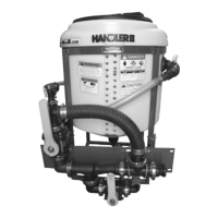
Step 3
Bypass valve installation
Attach coupler (25-M220200CPG) to discharge end of ven-
turi using (25-FC200) flange clamp and (25-150G) gasket.
Attach 2” manifold tee (25-M220TEE) to coupler using (25-
FC220) flange clamp and (25-200G) gasket. Make sure stem
of tee is pointed upwards.
Figure H1-4.10
Position manifold tee so it is tight against the left hand side
of the front (in-between tabs welded on the frame.) (See Fig.
H1-4.10)
Continue attaching manifold fittings using the appropriate
clamps and gaskets as shown. (See Fig. H1-4.10)
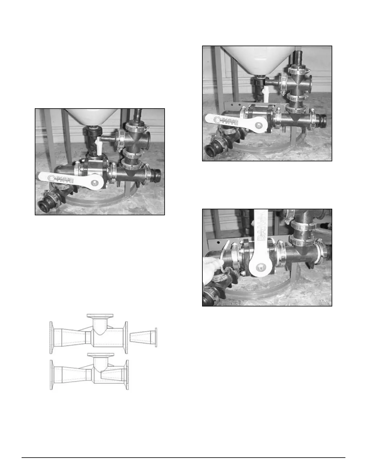
Note: Make sure venturi nozzle is in place before install-
ing venturi hose. Make sure arrow on venturi (Flow
direction) is pointed to the front.
Venturi Nozzle Placement
1.
2.
3.
4.
•
Step 4
Bracket installation
Figure H1-4.11
Install venturi bracket (86-H1i15VBPO) to tabs on Handler
frame as shown in Fig. H1-4.11 using ¼” x 1” bolts. Do not
tighten completely yet. (See Fig. H1-4.11)
Figure H1-4.12
Attach completed assembly to venturi bracket (86-
H1i15VBPO) using 3/8”x 2 ½” U-bolts (67-UB38-250)
(See Fig. H1-4.12)
Tighten all bolts and clamps
1.
2.
3.