45Handler I, II & III Operator’s Manual - October 2008
Handler III 3” Manifold Plumbing
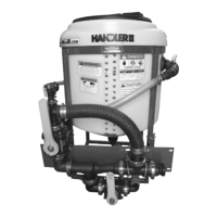
Figure H3P-4.4
Thread (without using sealant) 2” FPT x 2” hose barb 90
degree, 10-10930 to anti-vortex fitting on tank bottom. Turn
hose barb to desired position and tighten fly-nut. (See Fig
H3P-4.4)
NOTE: Check flynut on anti-vortex fitting and tighten as
necessary with pump pliers. Do not overtighten.
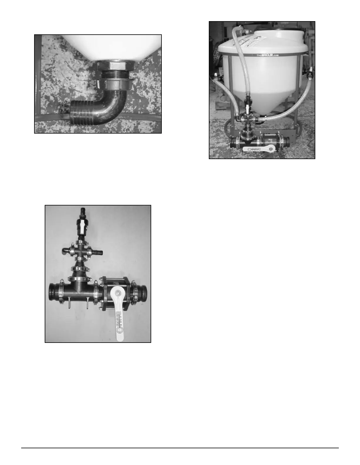
Figure H3P-4.5
Assemble 3” plumbing package. (See Fig H3P-4.5)
Install plumbing assembly to venturi bracket using three
3/8” x 4” U-Bolts 67-UB38-400. Tighten all bolts and U-
Bolts.
1.
•
2.
3.
Figure H3P-4.6
Measure, cut, and install 1” clear braided hose. (See Fig
H3P-4.6) Connecting agitation/rinse assemblies and rota
flush to cross assembly. Secure hose with MC12 clamps, 53-
75612.
Attach customer supplied 2” suction hose to 2” hose barb
assembly, 10-10930 on tank bottom. Secure with MC32
clamps, 53-75632 supplied.
Check and tighten all clamps and bolts as necessary.
NOTE: For optional recirculation package
installation instructions see page 26.
4.
5.
6.