17
HARDWARE FEATURES
Front Panel
3
4
6
7
11
1
2
5
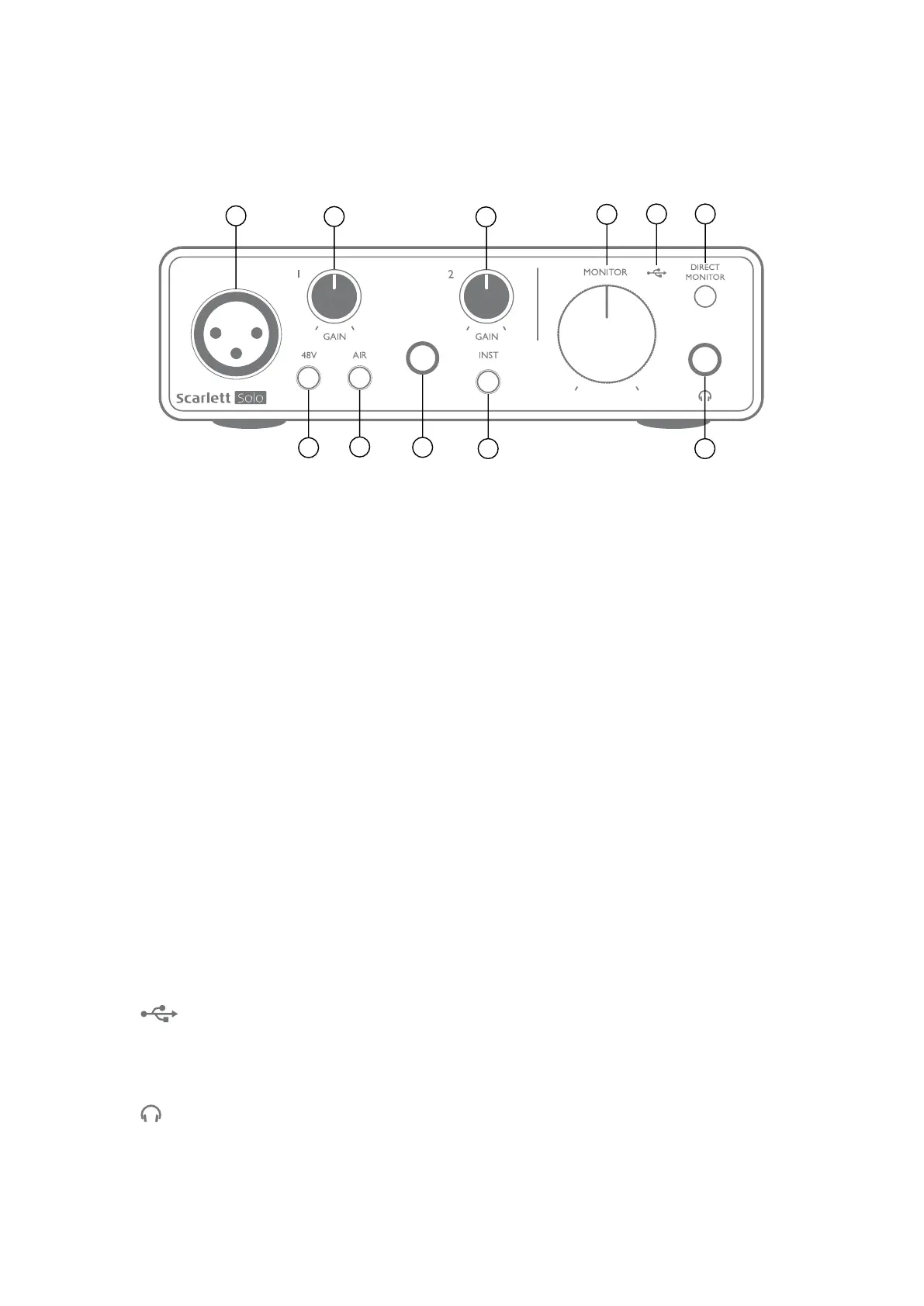
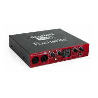
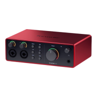
The front panel includes the input connectors for mic and line/instrument signals, and the input gain
and monitoring controls.
1. Input 1 – electronically balanced input via 3-pin XLR socket for microphones.
2. GAIN 1 – adjust the gain for the microphone signal at Input 1. The gain controls have tri-colour
LED ‘rings’ to conrm signal level: green indicates an input level of at least -24 dBFS (i.e.,
‘signal present’), the ring turns amber at -6 dBFS to indicate the signal is close to clipping,
and nally to red at 0 dBFS (digital clipping).
3. 48V – phantom power switch for mic input - enables 48 V phantom power at the XLR socket.
4. Input 2 – ¼” TRS jack socket to connect both instruments (unbalanced TS jack) or mono line
level (balanced) sources.
5. GAIN 2 – adjusts the gain for the line/instrument signal at Input 2. The gain control has a tri-
colour LED ring as [2].
6. INST – Instrument/Line level switch for Input 2 – switches gain to suit instrument or line level
signals. ‘INST’ illuminates red when Instrument mode is selected. Note that INST mode may
also be selected from Focusrite Control.
7. AIR – switch enabling AIR mode for the mic input. AIR modies the frequency response of
the input stage to model the classic, transformer-based Focusrite ISA microphone preamps.
‘AIR’ illuminates yellow when the mode is selected. Note that AIR may also be selected from
Focusrite Control.
8. MONITOR – main monitor output level control - sets the output level at the rear panel outputs
and the front panel headphone output.
9.
USB LED – a green LED illuminates when the Scarlett is connected and recognised by
your computer.
10. DIRECT MONITOR – selects monitoring of input signals (mixed with the DAW output) to be
directly from inputs (ON) or via the DAW (OFF).
11.
– ¼” TRS output jack. If your headphones have a ¼” TRS jack plug, connect them directly;
if they have a 3.5 mm TRS “mini jack”, use a TRS ¼”-to-3.5 mm jack adaptor. Note that it is
likely headphones tted with 4-pole TRRS plugs will not operate correctly.





 To Next Page