FO-4 I&T (Remastered Ver.1.2 ) 05-24-2015
arms, and with both sector adjustments loosened, check worm shaft bearing
adjustment by pulling up and pushing down on steering wheel. If looseness is
present, adjust bearings to a slight pre-load by removing a shim or shims from top
face of gear housing, after first removing steering gear cover and tube assembly
Fig. FO10. To clear gear assembly for removal, it will be necessary to remove hood,
battery and instrument panel.
Bearing adjustment is correct, when pull
required to rotate steering wheel through
center or straight forward position is 1-1/2
pounds with drag links disconnected and sector
mesh adjustments loosened. Measure pull with a
spring scale hooked to rim of wheel and take
the reading while wheel is in motion.
After completing worm shaft bearing adjustment,
readjust backlash of both sectors as outlined
in paragraphs 7 and 8.
11. OVERHAUL. Hood, battery and instrument
panel must be removed before steering gear unit
can be removed. After unit is cleared for
removal, disconnect both drag links at steering
gear arms, unbolt steering gear unit from
transmission housing and lift unit off of
tractor.
11A. Pull both steering gear arms off sector
shafts and unscrew cap screws holding sector
shaft housings to gear case. Remove both sector
gears and covers from sides of gear case Fig. FO8. To facilitate removal of –
these sub assemblies, turn them clockwise and they are withdrawn. Remove shaft tube
flange cap screws and lift assembly off of gear case. CAUTION: Do not turn worm
shaft if nut is near either end of worm as ball retainers may be damaged.
New sector shaft housing inner bushings are pressed into housing 1/8 inch below
face of hub . Outer bushings are installed flush or slightly below bottom of dust
seal counterbores. Bushings should be align reamed to 1.125 1.126. –
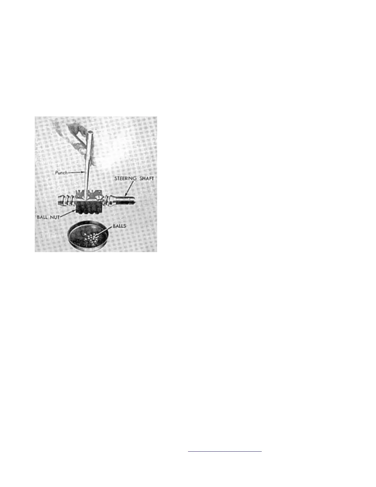
NOTE: Do not disassemble the unit shown in Fig. FO9. Any derangement of excessive
wear in any of the components of this screw shaft and ball nut assembly is
corrected by renewal of the nut and shaft unit Ford part 8N3575 as the individual
parts are not catalogued.
Install worm shaft and nut assembly with nut positioned at approximate center of
worm and adjust worm shaft bearing end play as described in paragraph . After
Connect/Report Errors – jcchapster@gmail.com
Fig. FO9 It is possible to –
disassemble the screw shaft and
ball nut assembly used in model
8N tractors but such procedure
is not recommended. Refer to
text.
 Loading...