FO-4 I&T (Remastered Ver.1.2 ) 05-24-2015
the quadrant position is correct, valve lever (38) will first contact the pump
housing at point A, just as the touch control lever reaches its full UP position on
the quadrant.
101A. If valve lever does NOT first
contact the pump housing
simultaneously with the touch control
lever arriving at the full UP
position, loosen the cap screws (Q-
Fig. FO78) in the quadrant support
plate and move the quadrant forward
or backward as required. Top face of
quadrant support plate should be
parallel with top of the attaching
plate on the lift cover after
adjustment is completed.
If touch control lever will not
remain in any set position tighten
the castellated nut at external end
of touch control lever shaft.
Recommended frictional drag is when a
4-5 pound pull at end of lever is
required to move the lever.
102. CONTROL SPRING. Check and
adjust implement control spring in
same manner as for models 2N and 9N
as per paragraph 100.
Adjustments described in paragraphs
103 and 104 can be made only when the
lift cover assembly is off the
tractor. The need for these
adjustments is when the lift cover
assembly has been overhauled or when
mechanical tampering has occurred.
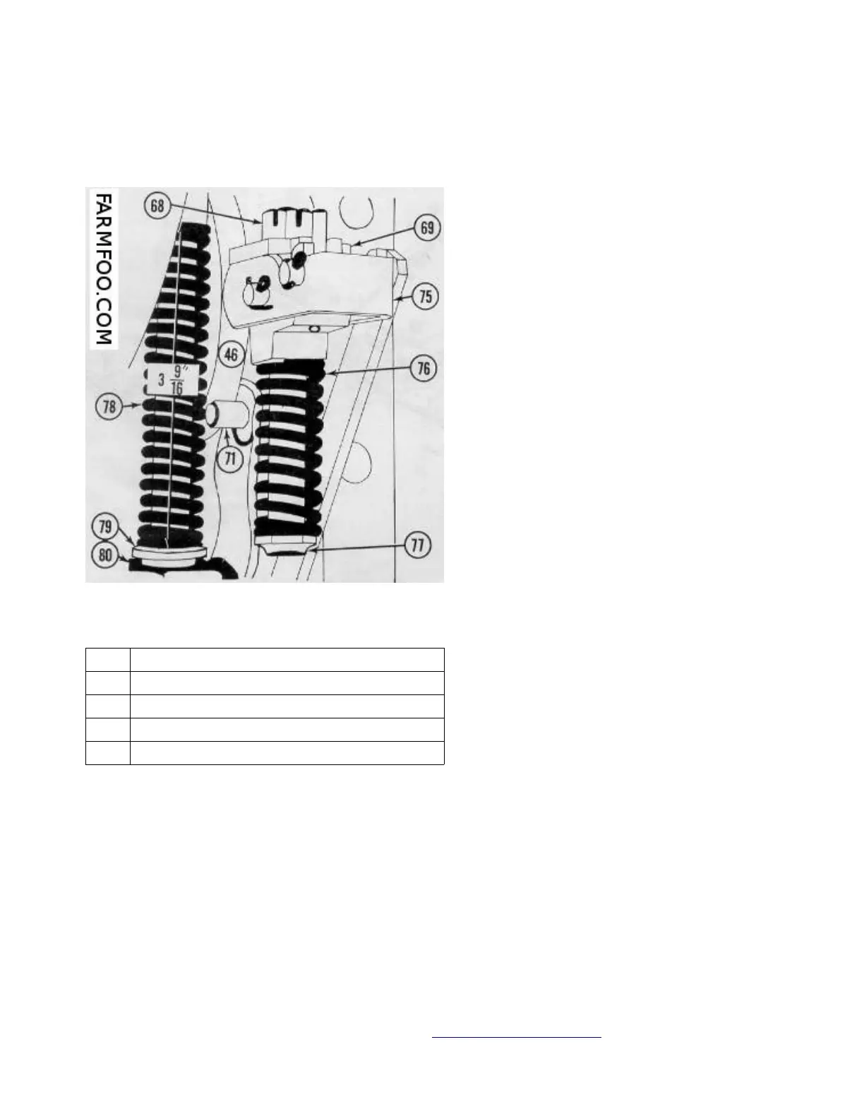
103. CONSTANT DRAFT SPRING. To adjust constant draft spring mount the lift cover
assembly in a vise with control spring up as shown in Fig. FO81. Disengage the
position control lever (62) by moving it to the forward down position. Measure the
length of the constant draft control spring (78) which should be 3-9/16 plus or
minus 1/64 inch. If spring is not within these limits adjust to 3-9/16 by means of
adjusting nut (81).
104. POSITION CONTROL SPRING. To adjust the position control spring, mount lift
cover assembly n a vise as shown in Fig. FO82, and engage the position control
Connect/Report Errors – jcchapster@gmail.com
Fig. FO81A - Closeup of control springs
and portion of linkage contained in
hydraulic lift cover on model 8N tractors.
46. Cam
69. Cam plate
71. Pin for position (drawbar) control arm
75. Position (drawbar) control cam
77. Position (drawbar) control
 Loading...