FO-4 I&T (Remastered Ver.1.2 ) 05-24-2015
this condition is incorrect adjustment of quadrant. Refer to paragraph 99 or 101.
PUMP R&R AND TEST
Models 2N-8N-9N
114. TEST PUMP. To check pump operating pressure when pump is installed, proceed
as follows: Remove hexagon head (1/2 x 20) cap screw (14-Fig. FO92) located at
right hand corner of pump base and in its place connect a pressure gauge of not
less than 1700 and not more than 2500 psi capacity. With the lift arms secured in
the full lowered position or weighted to prevent lifting, move the touch control
lever to the top position on the quadrant. The relief valve should open at a gauge
pressure of not less than 1600 psi.
If the pump does not deliver the
expected minimum pressure of 1600
pounds per square inch, check for a
faulty safety (relief) valve (30). To
check for this condition remove either
inspection cover from sides of rear
axle center housing. With the pump
running, there should be no visible
oil turbulence in the vicinity of the
safety valve. If turbulence is
present, remove the relief (safety)
valve and install a new one.
If the safety valve is considered to
be in operating condition by the
preceding check, and the expected
pressure is not obtained, the pump,
cylinder, and/or high pressure oil
tube is at fault. A visible oil spray
in the pump compartment of the rear
axle center housing indicates leakage,
the location of which can usually be
traced by visual inspection. If no oil
spray is evident, a further check
involving removal of the pump will be
necessary.
Connect/Report Errors – jcchapster@gmail.com
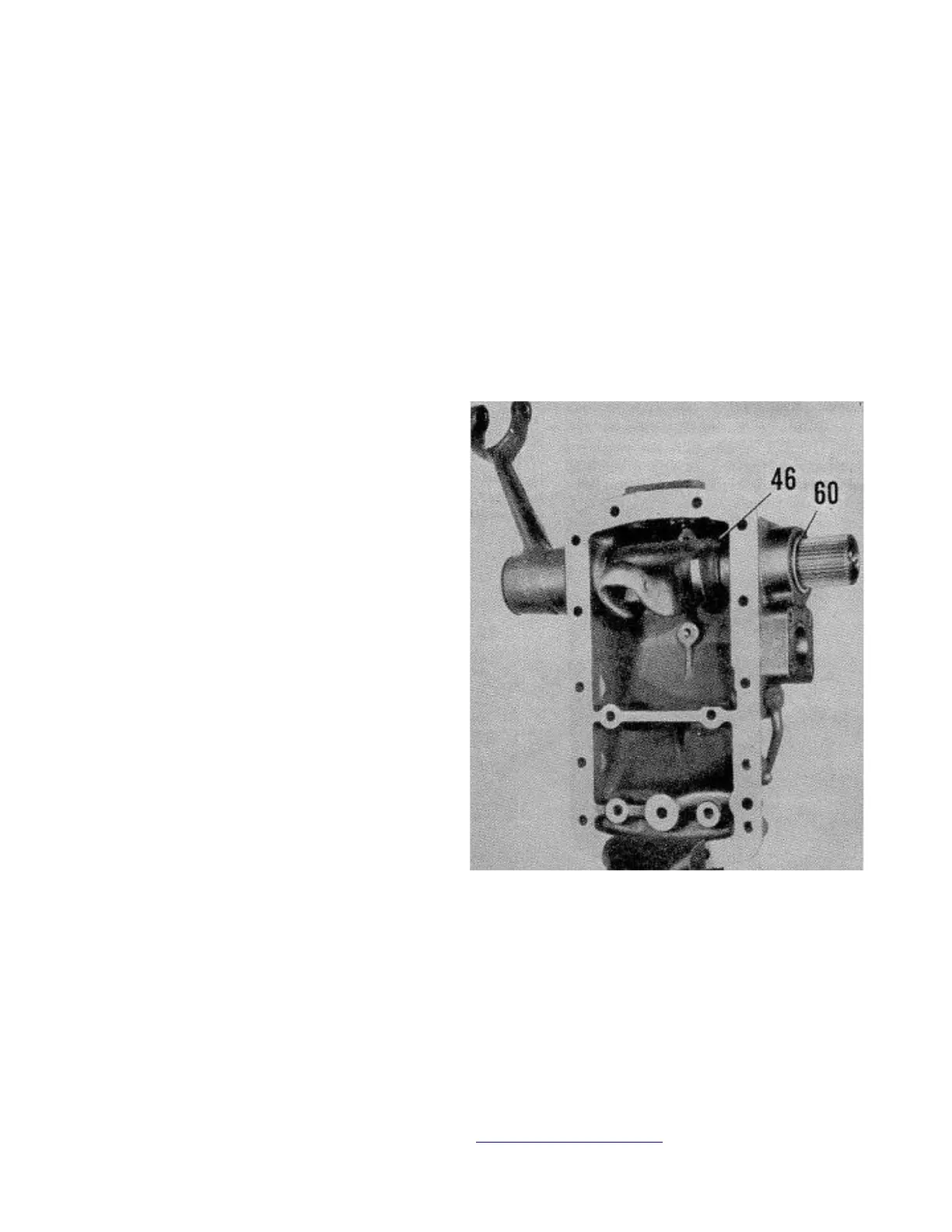
Fig. FO91 - Model 8N lift cover showing
first step in reassembly procedure.
 Loading...