FO-4 I&T (Remastered Ver.1.2 ) 05-24-2015
GOVERNOR
43. The governor, shown in Fig. FO-28 is a
variable speed, ball type, driven by engine
timing gears and interconnected with the throttle
linkage and carburetor throttle valve. Splash
lubrication is provided from timing gear case and
it is important that the large oil passage
opening in governor ball bearing carrier plate,
to be installed at top or up position to assure
proper lubrication. Further lubrication is
provided by an oil line which connects between
rear of governor housing and oil filter as shown
in Fig. FO29. Early model tractors were not
provided with this oil line but service parts are
available to permit this approved modernization.
44. ADJUSTMENT. The governor spring (2 Fig.–
FO28) should be a snug bit but should have no end
play and no pre-load. Spring may be adjusted by
bending the loop on the spring with pliers. Check
engine speed at Power Take-Off shaft or belt
pulley, after engine is warmed up. Correct
governed speed with hand throttle lever in last
quadrant notch or wide open is 727 to 800 PTO
shaft rpm, 2000 to 2200 engine rpm or 1358 to
1494 belt pulley rpm.
If crankshaft speed exceeds 2200 rpm or power
take-off speed exceeds 800 rpm with throttle
lever in last quadrant notch, turn in maximum
speed stop screw (Fig. FO28 - 5) until speed is
correct. If engine overspeeds before hand
throttle is wide open, adjust model 2N 9N–
linkage by holding throttle shaft lever at “A”,
Fig. FO30 and bending linkage until speed is
correct, or by lengthening governor link rod on
model 9N, as shown in Fig. FO31.
Connect/Report Errors – jcchapster@gmail.com
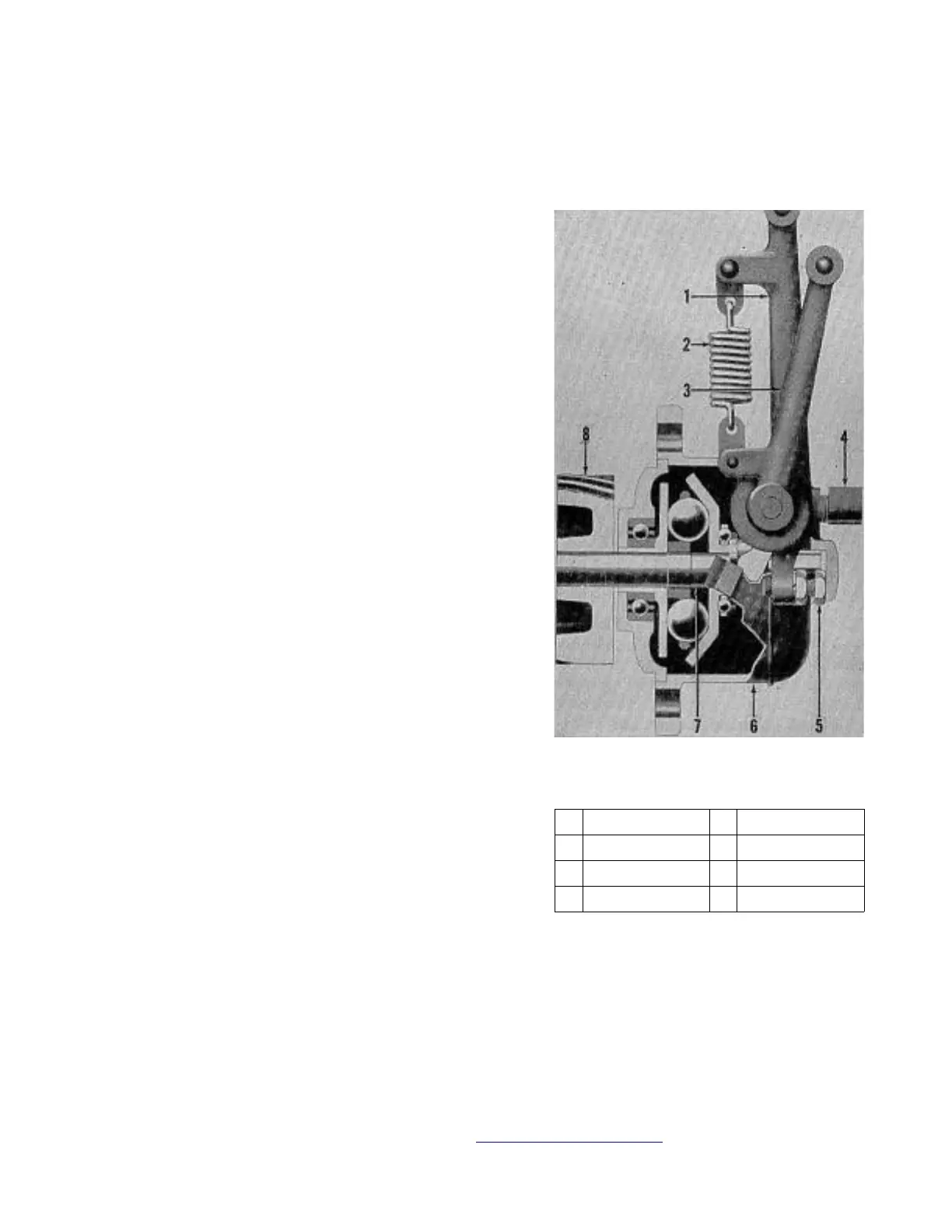
Fig. FO28 Novi ball type –
governor used on models 2N-8N-9N
tractors.
1. Inner lever 5. Stop screw
2. Spring 6. Housing
3. Outer lever 7. Flyball unit
4. Oiler elbow 8. Drive gear
 Loading...