FO-4 I&T (Remastered Ver.1.2 ) 05-24-2015
106. DISASSEMBLE AND OVERHAUL. Procedure
for disassembly of the lift cover assembly
is self evident by an examination of the
unit and reference to Fig. FO85. The general
order of disassembly is the ram cylinder
(50), control spring (42), lift control fork
and spring control fork (53). Remove cap
screws retaining one lift arm (59) to lift
shaft (45); then bump end of lift shaft
which will remove lift shaft ram arm (46)
and one lift shaft bushing (60). Push other
bushing from housing. Remove hand control
quadrant (56) and attached parts.
107. Clean all parts in an approved solvent
being sure to remove all gum, carbon or
varnish from the surfaces. Renew any worn
corroded or scratched parts. Clearance of
piston (48) in ram cylinder (50) should be
not less than
.0012 and not more than
.0025. Bushing (60) are presized and if
carefully installed will require no final
sizing after installation. Check linkage for
being bent or twisted and renew such damaged parts.
108. Reassemble the unit by reversing the disassembly procedure. When reinstalling
lift arms tighten the retaining cap screws until arm shaft binds, then loosen
screws until arms can be raised and lowered freely. After reinstalling unit to
tractor adjust the control spring and quadrant as in paragraphs 99 and 100.
Model 8N
109. R & R COVER FROM TRACTOR. To remove lift cover unit from tractor first
remove the tractor seat and the pin from the main control spring yoke (41-Fig.
FO78). Disconnect lift arms from leveling arms by removing cotter pins and clevis
pins. Move the touch control lever (57) (larger of two levers) to the down position
and the position control lever (62) (smaller lever) to the disengaged (down)
position. Place the lift arms in the down position. Remove approximately 14 cap
screws retaining lift cover to axle center housing and carefully lift the unit off
the tractor. After installing cover adjust the quadrant and main control spring as
outline in paragraphs 100 and 101.
Connect/Report Errors – jcchapster@gmail.com
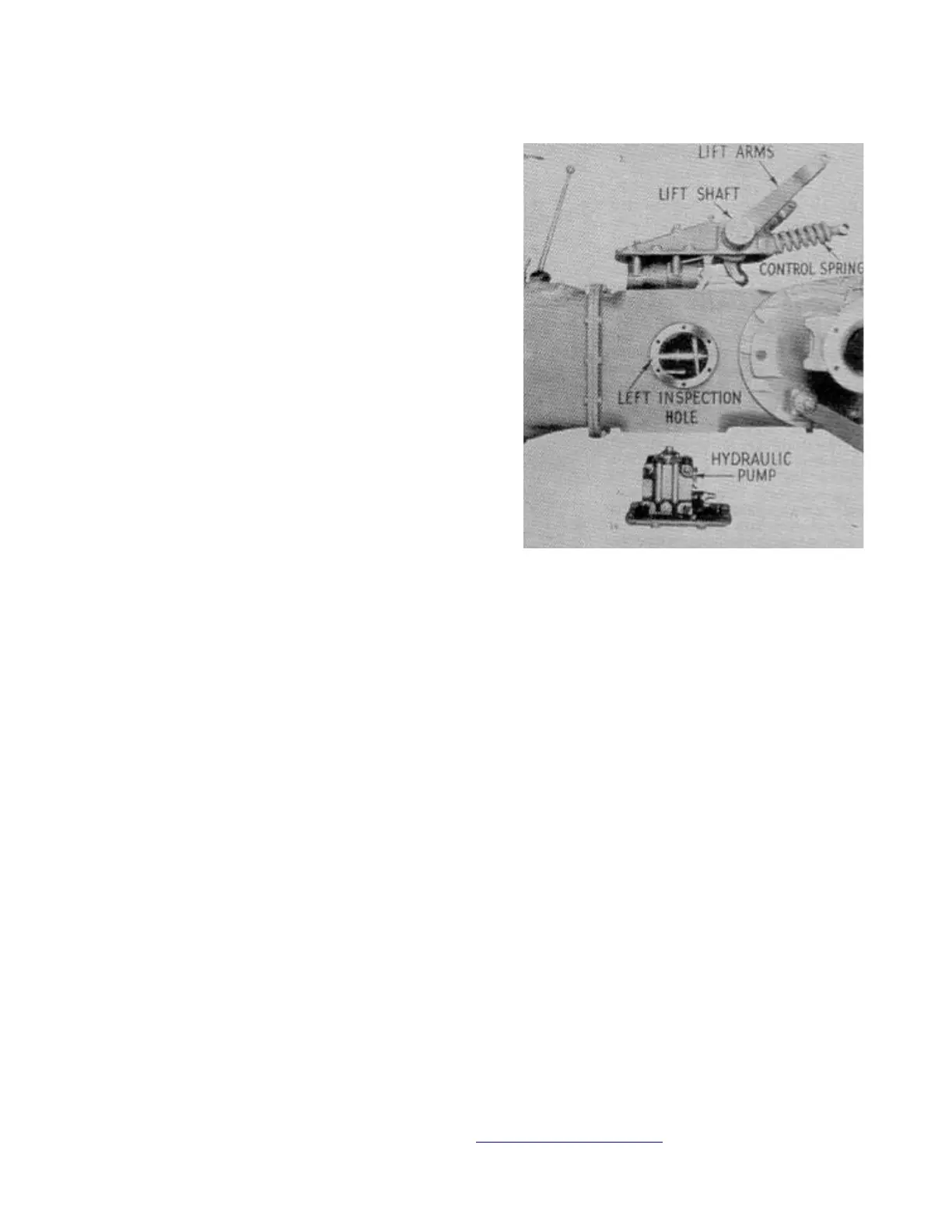
Fig. FO83 - Left cover assembly and
hydraulic pump being installed to
rear axle center housing.
 Loading...