We recommend the wireless accessories
which require only programming
FA62 Wireless keypad
FR11 Wireless button
Openers have a 12Vdc supply suitable
to power access controls and sensor
devices of your choice.
FA30 Photobeam
FA61 Keyswitch
VY805 Wired button
Wired connections are made to screw
terminals on the main PCB. They have
been colour coded for simplicity. All 5
wires connect to one corner of the PCB.
See below for wiring.
GREEN Button input
VIOLET +5Vdc (button com)
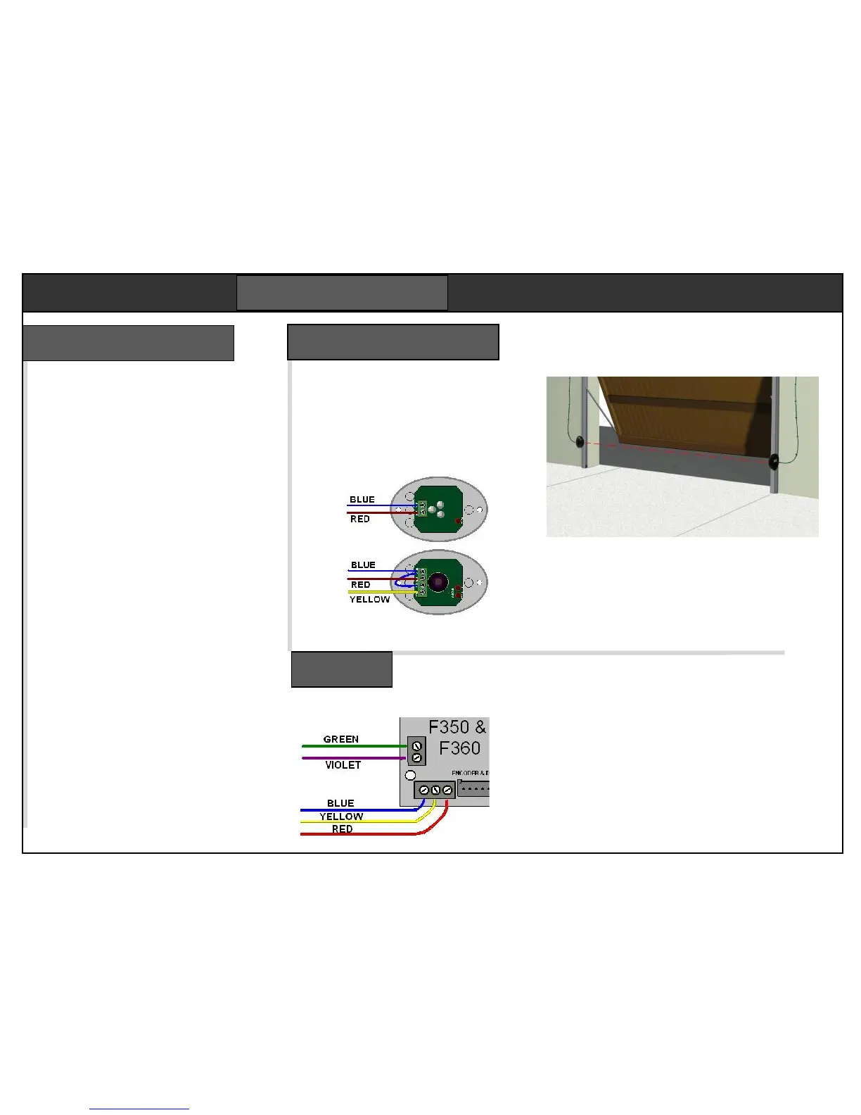
BLUE Ground (photobeam com)
YELLOW Photobeam input
RED +12/15Vdc
Refer to the wiring notes supplied with
each accessory for more information.
Button input GREEN & VIOLET
Keypad power BLUE (-) & RED (+)
Keypad contact GREEN & VIOLET
Safety edge BLUE & YELLOW
The FA30 optional photo beam prevents
the door closing if the beam is blocked
by a car or any other object. If an object
moves into the beam while the door is
closing, it will stop and re-open. Used
when the automatic closing is enabled.
This device requires a four core cable to each
side of the door frame. Mount the two photo
beam elements on brackets fixed to the inside
door frame 250mm above floor level. No door
parts must cross the beam in normal travel.
Keep the cable clear of moving door gear. Any
damage will stop the door closing.
The photobeam function must now be enabled
in the programming. See step 4.
There is a single PCB with a number of connectors
for dedicated functions. Two screw terminals in the
corner are for the accessory connections. Switch
the power off before taking the housing off.
There are two 2.5A fuses, one for the lamp, one for
the transformer. Bulb type is a 230Vac 25W E14
accessible through the white cover.