14
WWW.FORNEYIND.COM
•
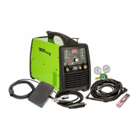
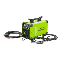
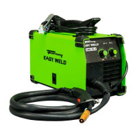
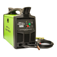
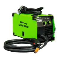
Attach the standard MIG welding gun to the EURO CONNECT on the front of the welder.
Gas Cylinder and Regulator Connection
The gas cylinder (not supplied) should be located near the rear of the welder, in a well-ventilated area and securely fixed
to the work bench or to the wall to ensure that it will not fall.
For safety and economy, ensure that the regulator is fully closed (turned counter-clockwise) when not welding and when
fitting or removing the gas cylinder.
• Turn the regulator adjustment knob counter-clockwise to ensure the valve is fully closed.
• Screw the gas regulator down on the gas bottle valve and tighten.
• Connect the gas hose to the regulator, securing with the clip/nut provided.
• Connect the other end to the GAS INPUT (14 for TIG welding or 15 for MIG welding) on the back of the machine.
• Open the cylinder valve, then set the gas flow to approximately 20 - 35 CFH (cubic ft. per hour) on the regulator.
• For MIG welding: Depress the gun trigger to ensure that the gas is flowing through the gun.
WARNING: Cylinders are highly pressurized. Handle with care. Serious accidents can result from improper handling
or misuse of compressed gas cylinders. Do not drop the cylinder, knock it over, expose it to excessive heat, flames or
sparks. Do not strike it against other cylinders or strike an arc on it.
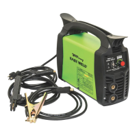
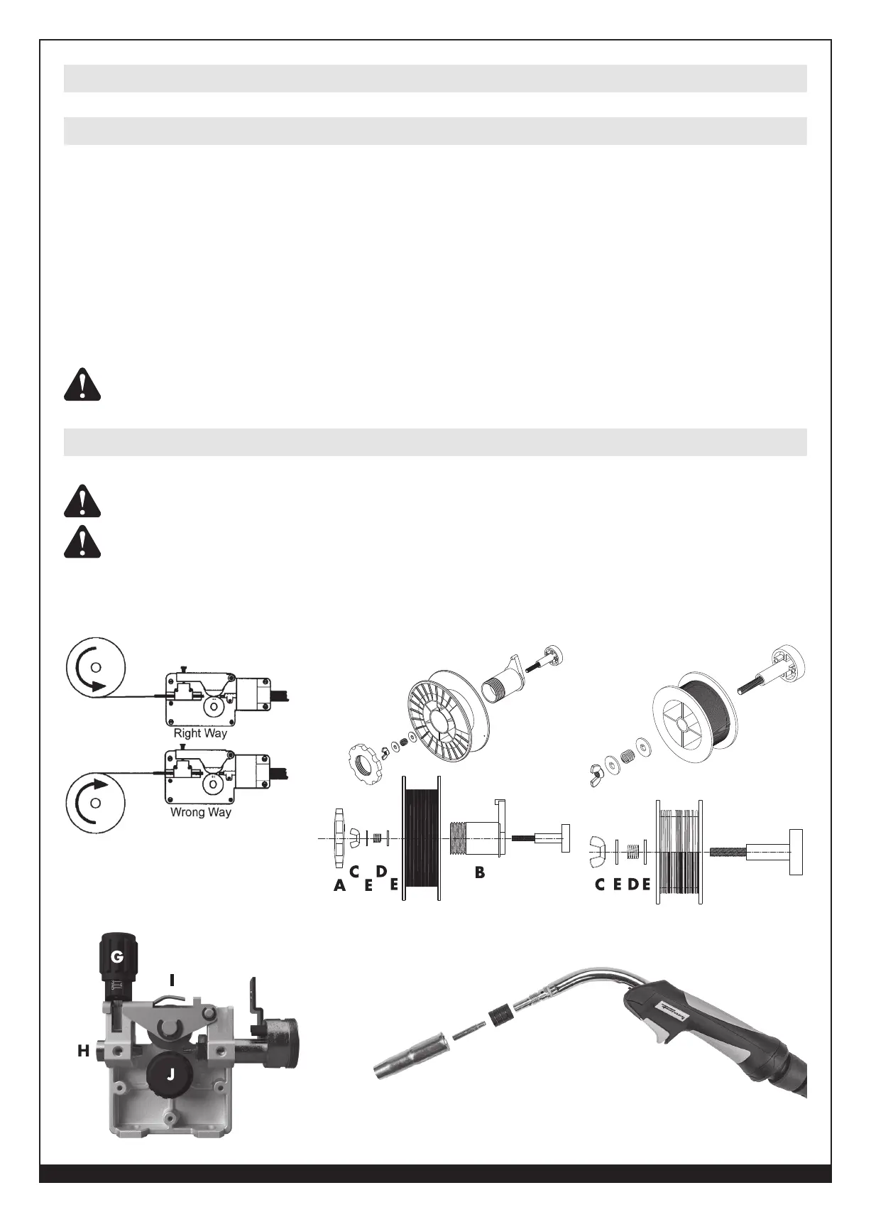
Installing the Welding Wire
ENSURE GAS AND ELECTRICAL SUPPLIES ARE DISCONNECTED. Before proceeding, remove the nozzle
and the contact tip from the gun.
WARNING: ELECTRIC SHOCK CAN KILL! Always turn the ON/OFF SWITCH to the OFF position and unplug
the welder’s INPUT POWER CABLE from the AC power source before installing wire. When the gun trigger is depressed,
the drive rolls, spool of wire, wire being fed, and electrode are all electrically live (hot).
Installing the MIG Gun Assembly
4
8
 Loading...