16
WWW.FORNEYIND.COM
1. Cut off the excess wire that extends past the end of the nozzle.
2. Fine tune the wire drive pressure with the pressure arm adjustment knob (G).
a. Turn the wire drive pressure adjustment knob clockwise, increasing the drive pressure until the wire seems to feed
smoothly without slipping. NOTE: If TOO MUCH pressure is applied you can crush the wire and create wire
feeding problems. If TOO LITTLE pressure is applied, the wire will slip on the drive rolls and wire will not feed.
b. When the drive pressure is set correctly, there should be no slippage between the wire and the drive roller. But if an
obstruction occurs along the wire feed path, the wire should then slip on the drive roller. This can be checked by
squeezing the wire between two fingers with moderate force as it comes out of the gun. If this stops the wire from
feeding, increase pressure until the wire feeds through your fingers without issue.
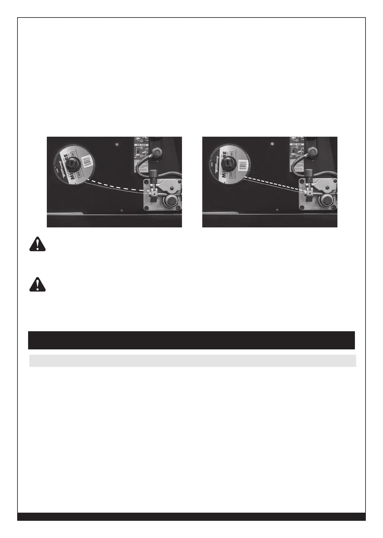
3. Double check your spool tension: After feeding the wire and releasing the trigger, the wire coming off the spool should
not remain under tension (in a straight line from the spool to the WIRE FEEDER). It should relax a little bit and take
on some of the curvature the coiled wire naturally reverts to. It should also not relax so much that the wire begins to
loosen on the spool.
CORRECT
INCORRECT
KEEP THE GUN STRAIGHT. WHEN FEEDING A NEW WIRE THROUGH THE LINER, MAKE
SURE THE WIRE IS CUT CLEANLY (NO BURRS OR ANGLES) AND THAT AT LEAST 1” FROM
THE END IS STRAIGHT (NO CURVES). FAILURE TO FOLLOW THESE INSTRUCTIONS COULD
CAUSE DAMAGE TO THE LINER.
WHEN CHECKING THE CORRECT EXIT OF THE WIRE FROM THE GUN DO NOT BRING YOUR
FACE NEAR THE GUN. YOU MAY RUN THE RISK OF BEING WOUNDED BY THE OUTGOING
WIRE. DO NOT BRING YOUR FINGERS CLOSE TO THE FEEDING MECHANISM WHEN
WORKING! THE ROLLS, WHEN MOVING, MAY CRUSH FINGERS. PERIODICALLY CHECK
THE ROLLS. REPLACE THEM WHEN THEY ARE WORN AND COMPROMISE THE REGULAR
FEEDING OF THE WIRE.
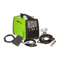
Performance Data Plate and Duty Cycle
On the machine, there is a plate that includes all the operating specifications for your new unit. The serial number of the
product is also found on this plate.
The duty cycle rating of a welder defines how long the operator can weld and how long the welder must rest and be
cooled. Duty cycle is expressed as a percentage of 10 minutes and represents the maximum welding time allowed. The
balance of the 10-minute cycle is required for cooling.
For example, a welder has a duty cycle rating of 30% at the rated output of 90A. This means with that machine, you
can weld at 90 A output for three (3) minutes out of 10 with the remaining seven (7) minutes required for cooling.
The duty cycle of your new welder can be found on the data plate affixed to the machine. It looks like the diagram
below. Referring to the sample below, the “X” row lists duty cycle percentages while the “I2” row lists the amp draw
corresponding to the duty cycle. Various duty cycles at other amperages are listed on your data plate.
Operation