HARDWARE INSTALLATION
16
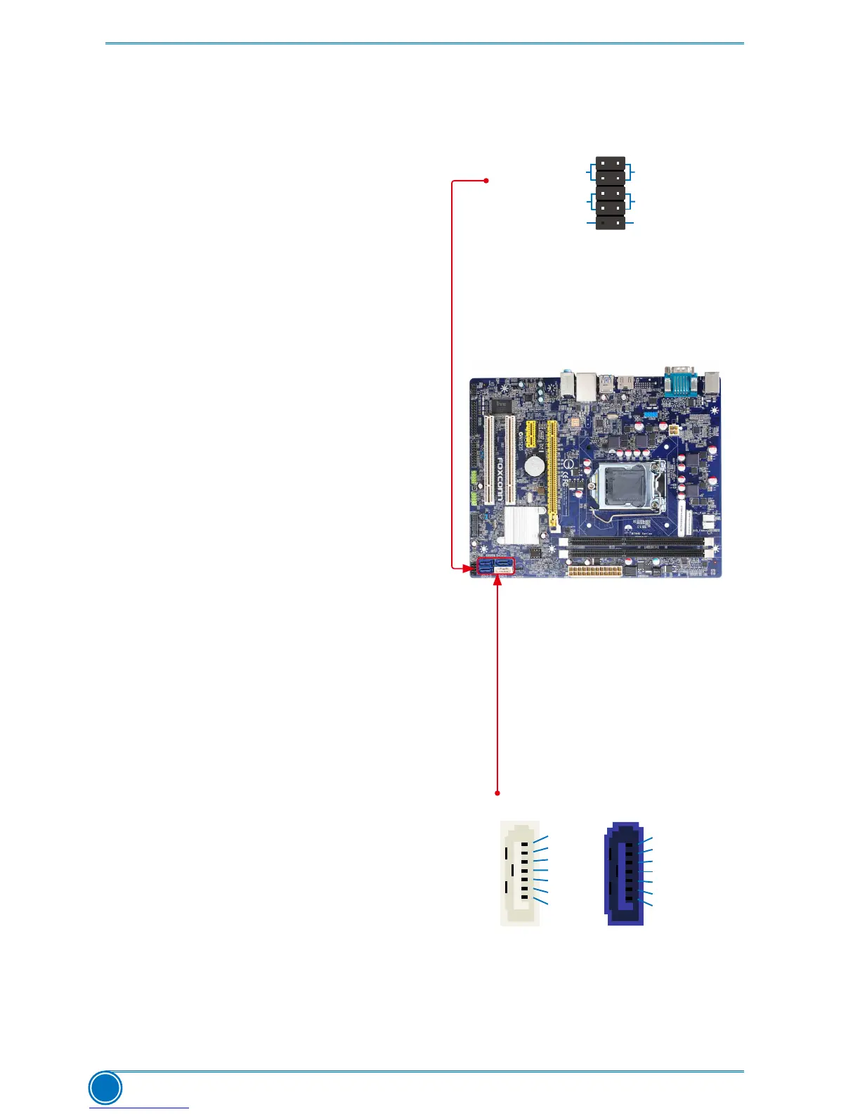
SATA_2/3/4
GND
TX+
TX-
GND
RX-
RX+
GND
1
GND
TX+
TX-
GND
RX-
RX+
GND
1
SATA_1
Front Panel Header: FP1
This motherboard includes one connector for
connecting the front panel switch and LED
Indicators.
Hard Disk LED Connector (HDD-LED)
Connect to the chassis front panel IDE
indicator LED. It indicates the active status
of the hard disks. This 2-pin connector is
directional with +/- sign.
Reset Switch (RESET-SW)
Attach the connector to the Reset switch on the
front panel of the case; the system will restart
when the switch is pressed.
Power LED Connector (PWR-LED)
Connect to the power LED indicator on the
front panel of the chassis. The Power LED
indicates the system’s status. When the
system is in operation (S0 status), the LED is
on. When the system gets into sleep mode (S1)
, the LED is blinking; When the system is in
S3/S4sleepstateorpoweroffmode(S5),the
LEDisoff.This2-pinconnectorisdirectional
with +/- sign.
Power Switch Connector (PWR-SW)
Connect to the power button on the front
panel of the chassis. Push this switch allows
the system to be turned on and off rather than
using the power supply button.
Serial ATA Connectors: SATA_1/2/3/4
The Serial ATA connector is used to connect with
SATA Hard Disk or CD devices which support this
feature.TheSATA_2/3/4allowsupto3GB/s
data transfer rate, the SATA_1 support SATA
3.0 specication, and allows up to 6GB/s data
transfer rate.
HDD-LED
RESET-SW
NC
+
- -
PWR-SW
+
PWR-LED
EMPTY
FP1
1 2
109
 Loading...