1
4
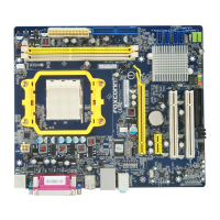
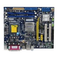
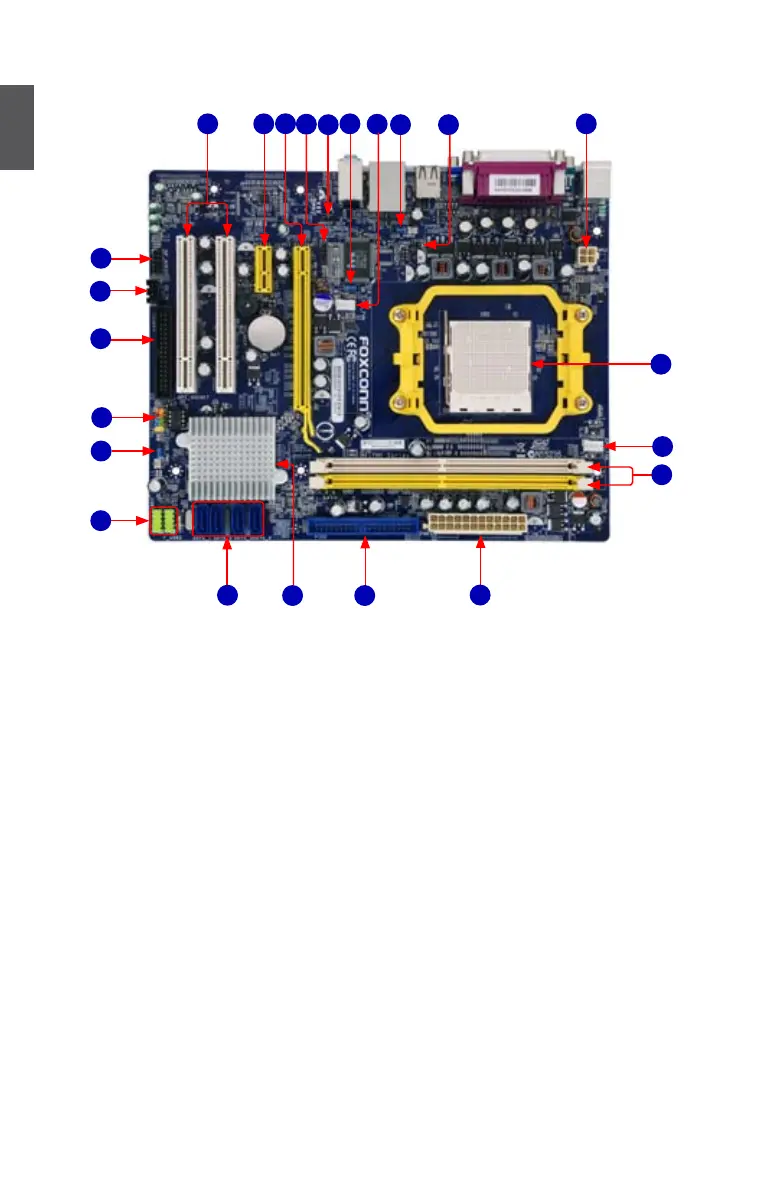
1-2 Layout
12
23
1
14
11
1. 4-pin ATX 12V Power Connector
2. Chassis Intrusion Alarm Header
3. USBPWR2 Jumper
4. System fan Header
5. Clear CMOS Jumper
6. S/PDIF Out Connector
7. IrDA Connector
8. PCI Express x16 Slot
9. PCI Express x1 Slot
10. PCI Slots
11. Front Audio Connector
12. CD_IN Connector
13. Floppy Connector
14. Front Panel Connector
15. USBPWR1 Jumper
16. Front USB Connectors
17. SATA Connectors
18. Chipset : NVIDIA Geforce 6100/
nForce 430
19. IDE Connector
20. 24-pin ATX Power Connector
21. DDR2 DIMM Slots
22. CPU_FAN Header
23. CPU Socket
Note : The above motherboard layout is for reference only, please refer to the physical mother-
board for detail.
16
13
21
5
9
10
3 2
4
6
7
8
15
17
19
20
18
22

 Loading...