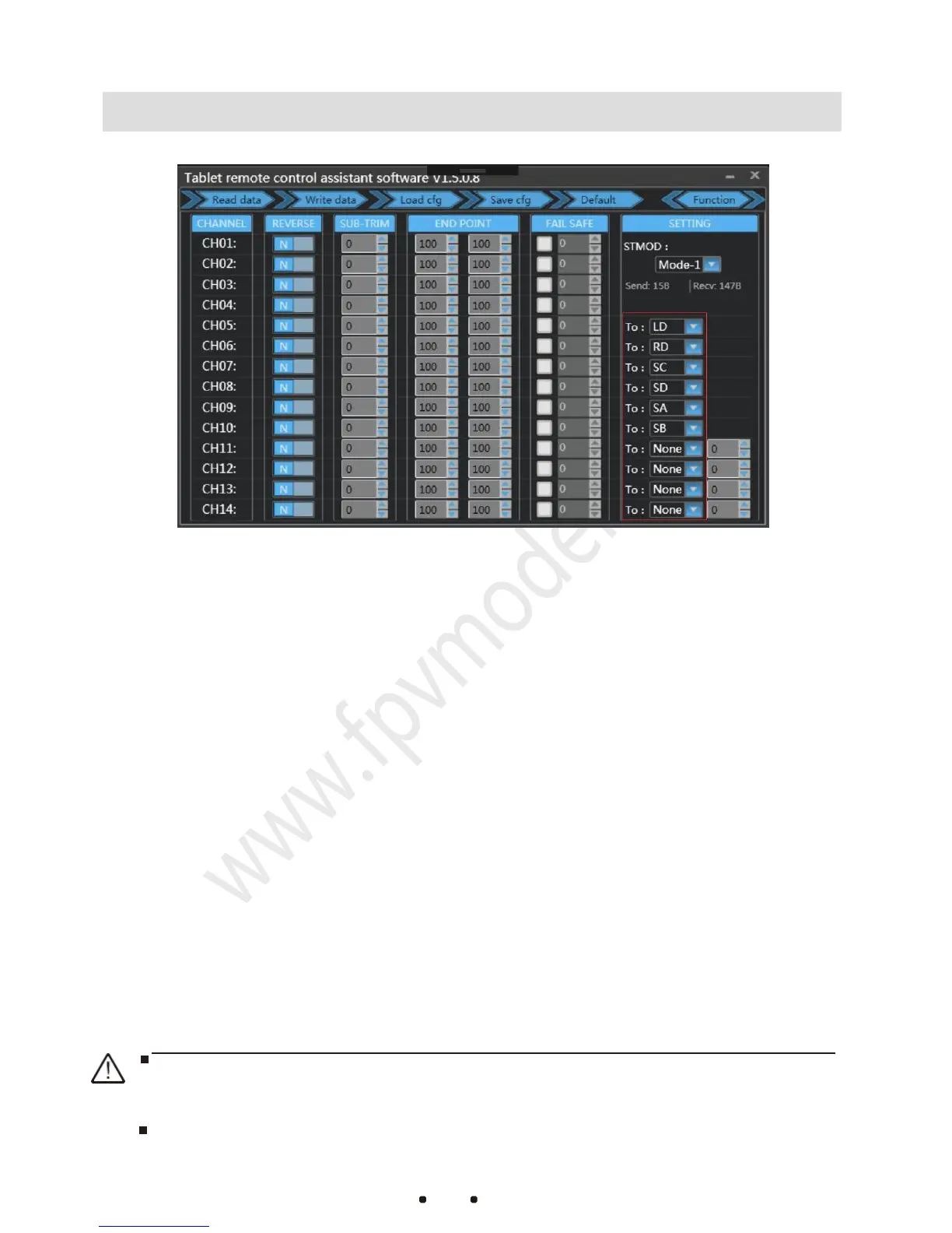
1. Click on “Function” button. The channel configuration interface is
shown as figure1-3. CH01-CH04 are default flight channels and
CH05-CH14 are auxiliary channels
2. The configuration of REVERSE, SUB-TRIM and END POINT are the same
as common remote controller setting method.(Please refer to
F
U
T
ABA
remote controller setting)
3. “FAIL SAFE” setting: Click on the white checkbox.When there is a √
in the white checkbox,the loss of control protection is working in that
channel.Set the value in corresponding input field with specified
output pwm value when the protection is enabled.
(After setting up,
please connect the receiver to your flight controller and switch off the
remote controller to check if the calibration is correct.)
4. The red marked box in Figure1-3 is the physical joystick configuration
outputs corresponding to CH5 - CH14. (One channel can be set to
one single joystick or multiple ones at once)
“Read data”Button:Read current configuration file
“Write data” Button:Write new configuration data
“Load cfg”Button:Load a different saved configuration file
“Save dfg”Button: Save the current configuration to a file for loading next time
After changing the configuration each time, you need to click the Write Data
button. The changed configuration will take effect.
The remote controller and the receiver have been paired before leaving the
factory. Do not re-pair and configure them without special circumstances.