F3Dn Service Manual Parts Replacement / Section 2.4
For Technical Support, Call 800-537-2653. Copyright 2006 Franke, Inc. All rights reserved.
2.4 Door Lift Slide Replacement
CONTINUED [Part No. 18000673]
22) Align the assembly and reinstall the four mounting bolts.
23) Reinstall hole covers, gaskets, door frame and doors on
door shafts. [Tip: See other Lane to verify assembly.]
24) Install Door [Open] Motor assembly starting with the two
bottom mounting screws. Remount Door Open Sensor &
bracket using the two upper motor mount screws.
25) Reconnect the two motor electric power connections:
[Red = positive; Black = negative].
26) Replace white plastic Door Cam Link, with Stop Screw to
the right side. [Note: Make sure bushings and spacers
are on both left and right cam pins, before replacing link.
27) Attach the spring retainer clip to right side Door Rotation
Block pin.
28) Using both hands, extend spring eye to left side Door
Rotation Block Pin. [CAUTION: Spring will be under
tension and may snap back.] Plastic bushings must be
installed in spring end loops, before mounting the spring.
29) Replace spring retaining clip and lock in place over pin.
30) Reposition the Door Lift Shaft in the Slide bearing
Assembly.
31) Reinstall the Door Lift Motor Assembly [P/N 19000161].
Make sure the gear box output shaft fits into the slot in
the lift cam.
32) Replace and tighten the four motor mounting screws
using your 5/32” [4 mm] Allen wrench.
33) IMPORTANT - Check the gap or calibration of the load
cell [weighs basket contents] under the motor by
inserting a .020” [.50 mm] feeler or gap gauge between
set post on left [open] side of load cell. [See Photo 6]
34) If load cell gap is larger or smaller than .020”/.50 mm,
adjust gap set nut located below left side of load cell.
35) Attach power service wires to Door Lift Motor. [Red =
positive, Black = negative]
Test the replacement Door Slide Lift as follows:
36) Plug in unit power cord to 120-volt power supply.
37) Turn on main power switch & pressing LANE-POWER
touch pad on front control overlay.
38) If LOAD READY light is on, position empty fry basket
under Hopper to activate fry loading cycle. [AUTO Mode]
39) If Lane properly dispenses fries, the Automation
Assembly is working properly.
40) Close rear service access panel and return F3D
Dispenser to normal operating location.
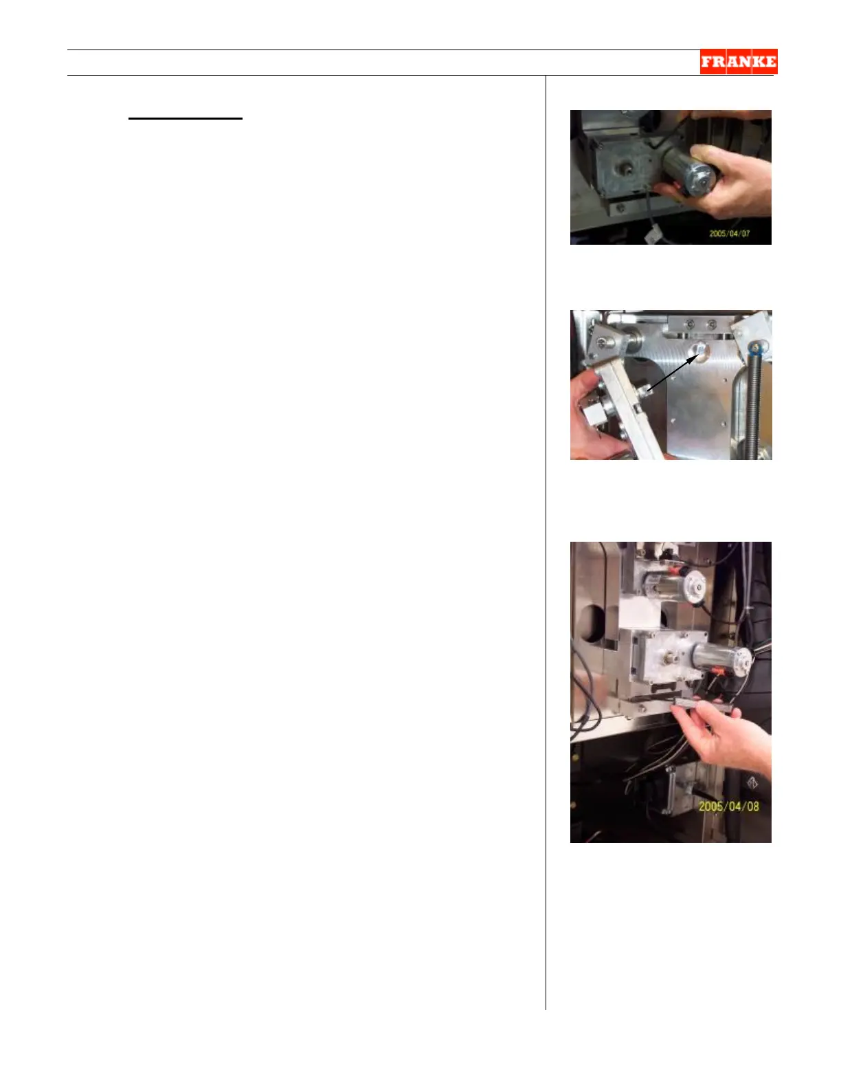
[Photo 4]
Remove the four motor mounting
screws from the Door Lift Motor.
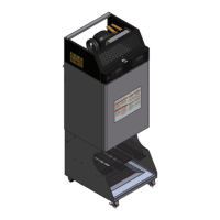
[Photo 5]
Ensure motor drive aligns with
the slot in the slide plate counter
bore.
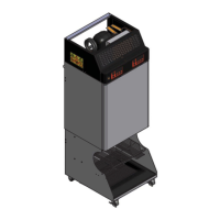
[Photo 6]
After replacing this motor, check
the gap on the load cell using a
.020 [.50 mm] feeler or gap
gauge.
Rev. 1 9/06