180
32
85
363
600
32.5
220
235
90
Ø120
Ø120
d2
d1
min 50
32.5
180
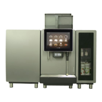
Installation and technical data
Page 14
30 mm foot 520 mm + 190 mm + 30 mm = 740 mm
40 mm foot 520 mm + 190 mm + 40 mm = 750 mm
70 mm foot 520 mm + 190 mm + 70 mm = 780 mm
100 mm foot 520 mm + 190 mm + 100 mm = 810 mm
Adjustable feet (optional)
Cross-section from above (grommet hole)Top view
Side viewFront view
Prepare a stable, ergonomic surface
(min. load capacity: 150 kg or 330.7 lb). The con-
trol panel should be at eye level.
Distance to the wall must be at least 50 mm. Clearance above the
machine must be at least 200 mm.
Adjustable feet (optional) can be used to compensate for unevenness
or height differences.
If optional add-on units are installed, 300 mm are required per add-on
unit.
Observe the connection requirements of the add-on units.
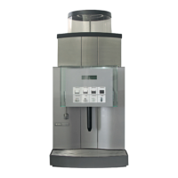
Installation dimensions of the Spectra
Dimensions of the Spectra

 Loading...