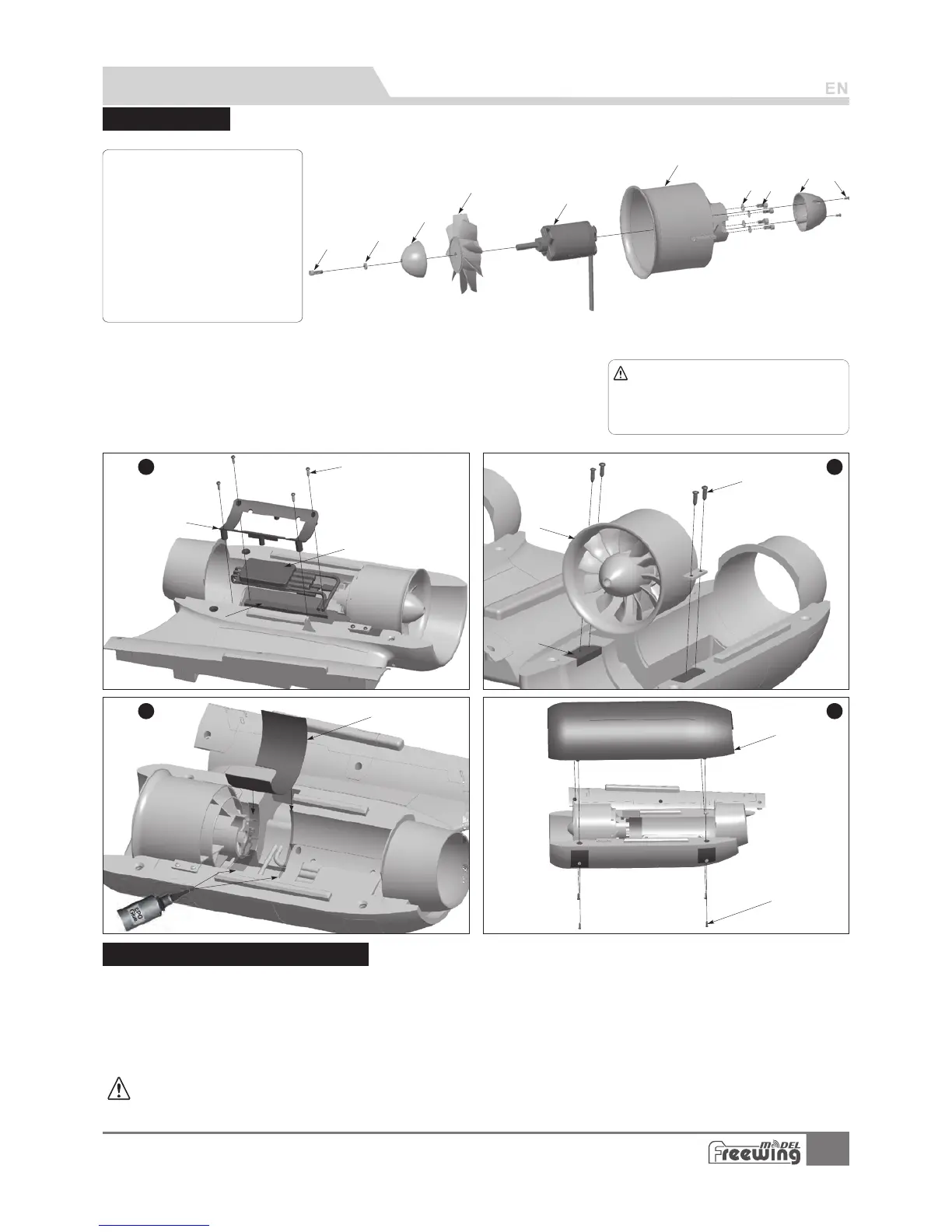
Motor installation
A
B
C
D
E
F
G
H
I
J
A
B
C
D
E
F
G
H
I
J
A-
B-
C-
D-
E-
ESC fixed mount
ESC
ESC fixed part
Screw (PA3x8 4pcs)
Power system fixed mount
F -
G-
H-
I -
J -
80mm EDF power system
Screws (PWA3x8 4pcs)
Plastic cover
Engine compartment cover
Screws (PA3x8 4pcs)
Accessories Description
Refer to the following diagram to install the ESC and power system:
Note: When ESC and battery connected, do
not touch them by hand to avoid accidental
injury. When testing an EDF, use a proper test
stand. Don't touch the EDF wihile testing
Step
2
Step
3
Step
4
Step
1
Standard version
A -
B -
C-
D-
E -
F -
G-
H-
I -
J -
Screw
Motor spinner
Cup head screws (M3x7 4pcs)
Washer
80mm ducted fan frame
for outrunner motor
3530-1900KV motor
80mm 9-blade ducted fan
Spinner
Washer
Cup head screws (M3x12 1pcs)
1. We have optional power systems available for the A-10.You may want to use one of these, just follow the above
steps, the dimensions are suitable for all Freewing 90mm EDF power system and 130A ESC.
2. ESC cable specification:
The cable length for motor output port: 100mm
The cable length for power port: 200mm
3. Note:An alternate brand of power system and ESC might not fit in this engine compartment, check the
dimensions before purchasing.
90mm EDF power system instruction
12
A-10 Thunderbolt II
Item No.:FJ311