PNP Assembly instructions
Servo lnput
Receiver
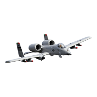
A-10 Thund erbolt II
6
5
4
3
1
2
E L E
T H R
R UD
GEAR
Nose Steering
GEARDOOR
Landing lights
FLAP
GEAR
RUD
E L E
A I L
T H R
1
6
5
A I L
FLAP
GEAR
LIGHT
Main wing control board(Right)
Main wing control board(Left)
1
6
5
A I L
FLAP
GEAR
LIGHT
Landing lights
Landing gear door
Landing gear
Nose steering
Rudder
Throttle
Elevator
EC5
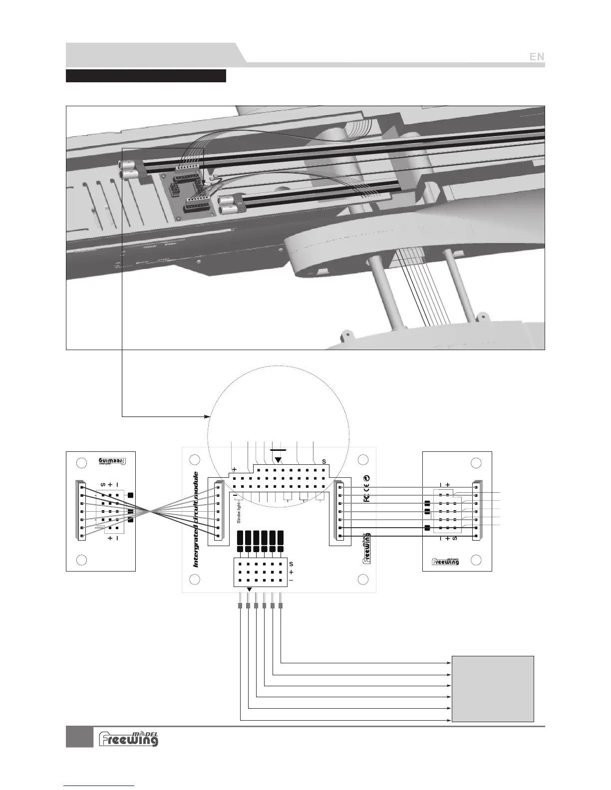
A-10 Thunderbolt II uses ribbon wires for convenience. Please refer to the following photo for connecting the electronic
equipment.
Control board connection diagram
Airleron
Flap(Two)
Landing gear
Wing tip lights
Flap(One)
Strobe light
Connect the aileron channel to the receiver
Connect the elevator channel to the receiver
Connect the throttle channel to the receiver
Connect the rudder channel to the receiver
Connect the landing gear channel to the receiver
Connect the flap channel to the receiver
RECEIVER
7
A-10 Thunderbolt II
Item No.:FJ311