Fontaine Fifth Wheels
General Information
The Fontaine sliding fifth wheel mount is designed to
provide optimum axle loading for maximum tractor
use with different lengths and types of trailers. The
sliding fifth wheel mount is used with the Fontaine
H5092 series, and 6000/7000 No-Slack II series fifth
wheels, and is equipped with either an air-operated
release slide (AWB or HAWB models), or a manual
release slide (MWS or HMWS models).
On Fontaine fifth wheels kingpin release is accom-
plished by activating a manual lock control handle
located on either the right side or left side of the fifth
wheel. Kingpin lockup occurs when the kingpin is
forced into the jaws and the lock control handle
moves to the locked position.
The fifth wheel top plate is mounted on a slide as-
sembly, which is attached to slide rails that are
mounted on the vehicle frame. The slide rails permit
forward and rearward movement of the slide assem-
bly, allowing for optimum weight distribution over the
tractor axles.
Slots are evenly spaced along the slide rails, and
retractable tapered wedges are positioned through
the slots to hold the fifth wheel in the desired posi-
tion. See Fig. 10.13 or Fig. 10.14.
The slide portion of the sliding model may be at-
tached to either an air-operated release slide, or a
manual release slide.
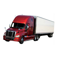
The air-operated release slide contains an air cylin-
der that locks and unlocks the fifth wheel slide. See
Fig. 10.13. The air cylinder is activated by a two-
position air-control valve in the tractor cab.
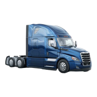
The manual release slide contains a slide release
pull handle, located on the left side of the fifth wheel,
which locks or unlocks the fifth wheel slide. See
Fig. 10.14.
Fifth Wheel Lock Mechanism for Trailer
Kingpin
(Fig. 10.15)
The Fontaine fifth wheel lock mechanism for the
trailer kingpin consists of a spring-loaded jaw and a
sliding wedge.
The jaw and wedge each have a pin permanently
attached. The pin on the jaw and the pin on the
wedge fit into elongated notches in the lock control
handle. The notches in the handle control the limit of
movement for both the jaw and wedge. The notches
are arranged so that the wedge is actuated first dur-
ing release of the kingpin.
During lockup, the jaw is moved first with the spring-
loaded wedge being allowed to slip in place against
07/25/95
f310189
1
2
1. Locking Wedge 2. Air Cylinder
Fig. 10.13, Air-Operated Sliding Fifth Wheel Mount,
AWB Model
07/25/95
f310190
1
2
1. Locking Wedge
2. Slide Release Pull Handle
Fig. 10.14, Manual Release Sliding Fifth Wheel Mount,
MWS Model
Fifth Wheels and Trailer Couplings
10.11