S70-101SM
Page 11
Frick XJS and XJF Rotary Screw Compressor
Service Manual
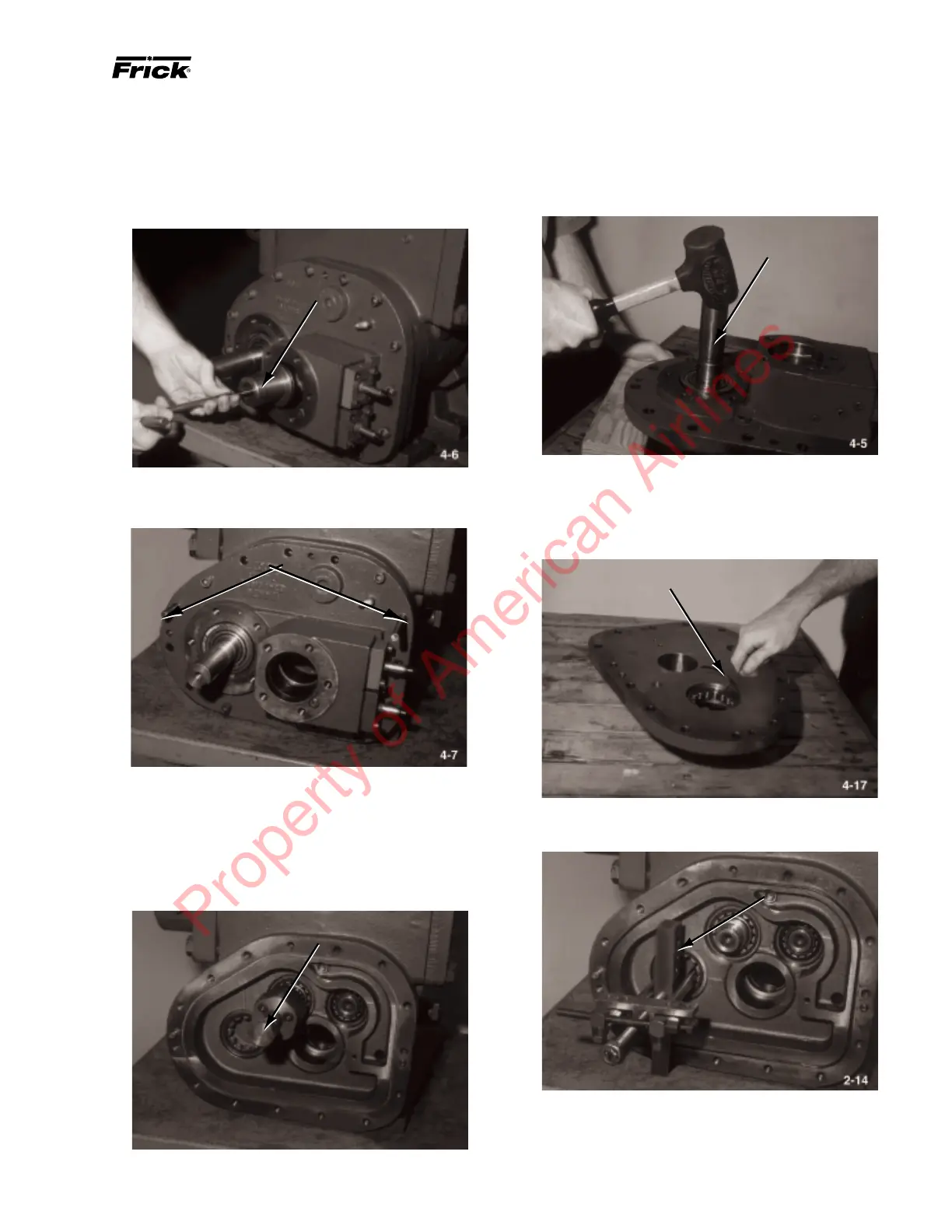
6. Thread T-wrench into slide stop piston (26, Figure 1-4);
remove slide stop piston with glyd-ring (10, Figure 1-4) and
o-ring (11, Figure 1-4). If glyd-ring and o-ring are to be
replaced, cut glyd-rings off of stepper piston using knife and
remove and discard o-rings.
10.With gear cover elevated on wood blocks, remove jackshaft
and gear assembly from cover by tapping on outboard end of
jackshaft with rubber mallet; remove jackshaft, gear assem-
bly, and outboard section of inner race of four-point contact
ball bearing (9).
JACKSHAFT
11. Remove remaining section of four-point bearing from
gear cover.
12. Remove retaining ring (12) from gear cover using screw-
driver.
RETAINING RING
13. Remove outer race of roller bearing (11) from gear case
using Bearing Puller (Owattona Tool Co. p/n 943).
BEARING PULLER
NOTE: If replacement Jackshaft Kit is used, steps 14
through16 do not apply.
SLIDE STOP PISTON
7. Remove two capscrews (1) from opposite sides of gear
cover (2). Install two 12mm guide pins (3
1
/2-inches long).
8. Remove remaining capscrews from gear cover. Thread two
12mm capscrews into jacking holes in gear cover and spread
cover away from rotor casing (3). Hold on to jackshaft and
remove gear cover and o-ring (51).
9. Attach Pinion Gear Puller to pinion gear (14); remove
pinion gear from male rotor (47).
PINION GEAR PULLER
12MM GUIDE PINS
Property of American Airlines