S70-101SM
Page 14
Frick XJS and XJF Rotary Screw Compressor
Service Manual
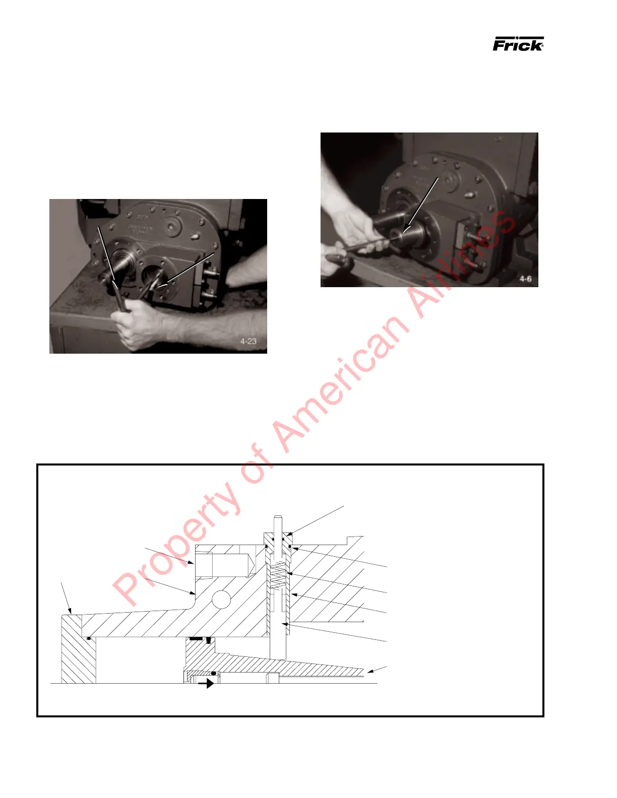
7. Thread T-wrench into slide stop piston (26); remove
piston with its glyd-ring and o-ring. If glyd-ring and o-ring
are to be replaced, cut glyd-ring off of slide stop piston and
remove o-ring with a knife.
SLIDE STOP PISTON
8. Remove compressor slide valve indicator position switch
cover; remove slide valve position switch.
9. Remove rod guide (5, Figure 1-5) with o-rings (2 and 3,
Figure 1-5), indicator rod spring (4, Figure 1-5), and indica-
tor rod (6, Figure 1-5); remove o-rings from rod guide.
10. Thread T-wrench into slide stop (25). While pushing in
against spring pressure, remove 8mm screw (threaded into
slide stop) through oil drain hole; remove slide stop.
Figure 1-5. Slide Valve Indicator.
1
9
2
3
4
5
6
7
8
1. Wiring Connection
2. O-Ring
3. O-Ring
4. Indicator Rod Spring
5. Rod Guide
6. Indicator Rod
7. Slide Valve Piston
8. Cylinder Cover
9. Discharge Casing
4. Place suitable drain pan under slide stop cover (30); remove
capscrews (7, Figure 1-2) securing slide stop cover to gear
housing (2). Remove slide stop cover and o-ring (32).
5. Thread 8mm T-wrench into stepper piston and push piston
in against spring force. With finger through oil drain hole,
push in against spring force and feel along bottom of slide
stop. When threaded hole in slide stop is located, insert an
8mm screw through oil drain hole and thread into slide stop.
STEPPER PISTON
8MM T-WRENCH
6. Remove stepper piston with its glyd-rings (10 and 28) and
o-rings (11 and 29). If glyd-rings and o-rings are to be
replaced, cut glyd-ring off of stepper piston and remove o-ring
with a knife.
Property of American Airlines