S70-101SM
Page 21
Frick XJS and XJF Rotary Screw Compressor
Service Manual
24. Install bearing spacer (32) over male rotor shaft.
inner race of roller bearing and inner race of ball bearing. If
clearance is greater than .003-inch, install shims in casing
bore
between roller bearing outer race and ball bearing outer race.
NOTE: Shim thickness is determined by amount of rotor
movement beyond the .0015 to .003 specifications.
Example #1
Measured end clearance = .005 inch
Desired normal end clearance = .002 inch
Desired shim size (location) = .003 inch between
outer race
Example #2
Measured end clearance = .0005 inch
Desired normal end clearance = .002 inch
Desired shim size (location) = .0015 inch between
outer race
Example #3
If end clearance is .000 inch, begin by placing .001
inch shim between inner races to extablish move
ment of the rotor.
NOTE: Installing shims will necessitate removal of dis-
charge casing. (Refer to steps 8 through 15 of para-
graph1.4.1.)
21. After attaining proper clearance, use drift tool to bend one
tab of lockwasher on end of female rotor shaft into one of the
recesses of locknut. This secures locknut in place and
prevents
it from turning on rotor shaft. Always use new
lockwashers,
never reuse lockwashers removed during disassembly.
22. Remove locknut (36), lockwasher (35), Spacer Tool, and
bearing spacer (32) from male rotor shaft.
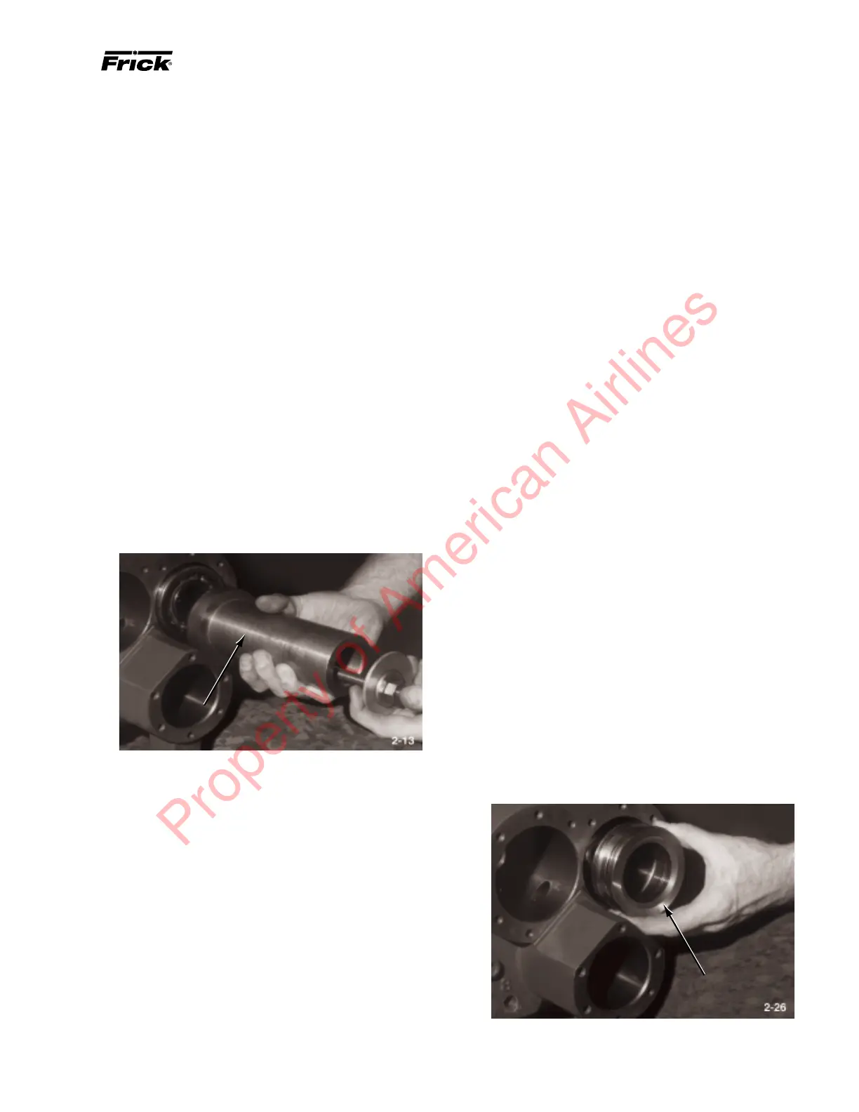
23. Place new o-rings (27 and 29) on balance piston (33) and
new o-ring (29) on piston sleeve (30). Assemble balance
piston, wave spring (31), and balance piston sleeve and install
assembly over male rotor shaft. Balance piston faces out.
BALANCE PISTON
14. If same rotor pair is to be reinstalled, place original shims
(removed in steps 14 and 15 of paragraph 1.4.1) over male and
female rotors and against roller bearings. If a new rotor pair is
being installed, use shims that were calculated in step 7, this
section. See Figure 1-6 for shim placement and correct orien-
tation of bearings.
NOTE: Use 12mm T-wrench threaded into opposite end
of rotor to prevent rotor from turning while using Dis-
charge Ball Bearing Installation Tool.
15. Using Discharge Ball Bearing Installation Tool, install
two angle contact ball bearings (26), one at a time, on female
rotor shaft. Ensure that bearings are installed with closed side
of inner races back-to-back (identification markings on bear-
ings facing away from each other). See Figure 1-6 for correct
orientation of bearings. (A .002-inch shim is required between
inner races when wave spring is used on bore cover.)
NOTE: Use 12mm T-wrench threaded into opposite end
of rotor to prevent rotor from turning while using Dis-
charge Ball Bearing Installation Tool.
16. Using Discharge Ball Bearing Installation Tool, install two
angle contact ball bearings, one at a time, on male rotor shaft.
Ensure that bearings are installed with closed side of inner races
facing outboard (identification markings on bearings facing
inboard). See Figure 1-6 for correct orientation of bearings.
DICHARGE BALL BEARING
INSTALLATION TOOL
17. Install lockwasher (35) and locknut (36) on female rotor
shaft; tighten locknut with spanner wrench to 150 ft.-lb. (204
Nm)on the 120mm and 90 ft.-lb. (122 Nm) on the 95mm. DO
NOT bend tab.
18. Install bearing spacer (32) and Spacer Tool (1
15
/16 OD x
1
9
/16 ID x
7
/8-inch thick – used to take place of last bearing)
on male rotor shaft.
19. Install lockwasher (35) and locknut (36) on male rotor
shaft; tighten locknut with spanner wrench to 150 ft.-lb. (204
Nm)on the 120mm and 90 ft.-lb. (122 Nm) on the 95mm.. DO
NOT bend tab.
20. With Air Cylinder Tool still attached to drive end of
compressor, take same measurements as in step 13, this
section. Measured end clearances should be .0015 to .003-
inch. Record measured end clearances on Table 1.1. If clear-
ance is less than .0015-inch, install shims on rotor between
Property of American Airlines