Page 18
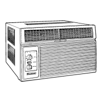
Figure 5: Fan Motor
4. Apply "live" test cord probes on red wire and
common terminal of capacitor. Motor should run
at low speed.
5. Apply "live" test cord probes on each of the
remaining wires from the speed switch or system
switch to test intermediate speeds.
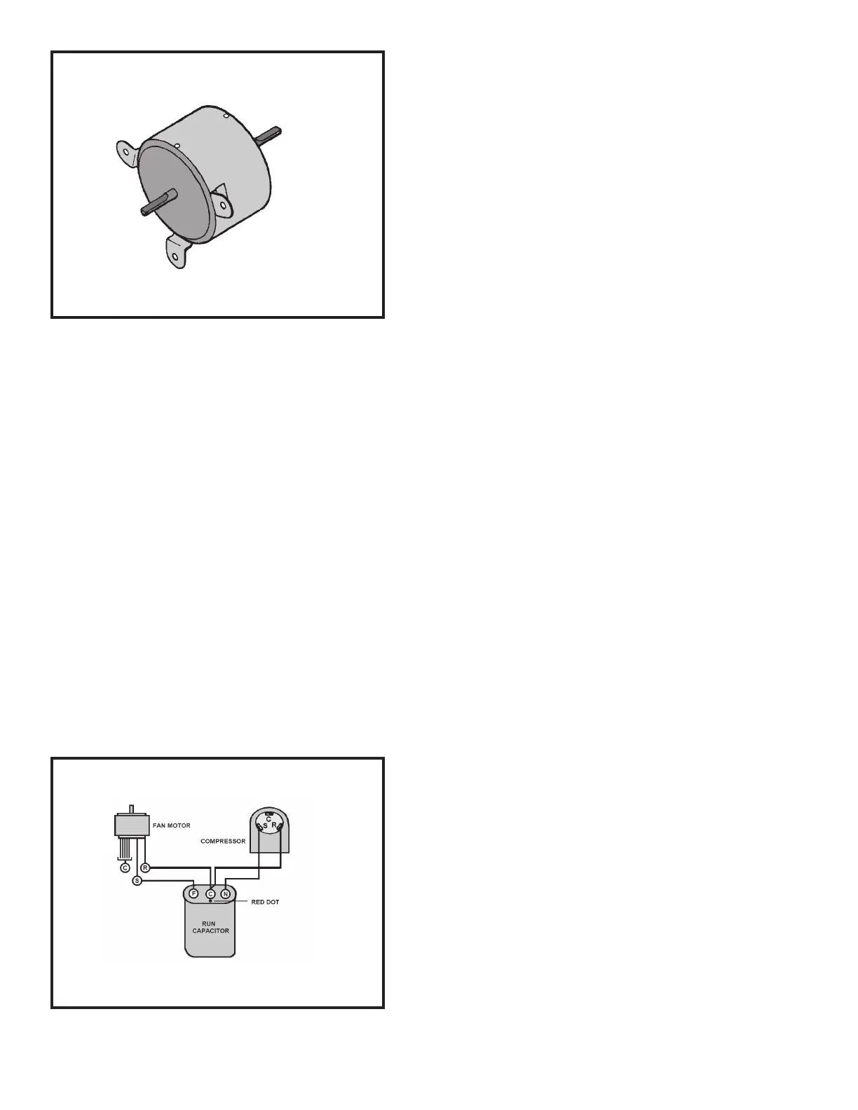
CAPACITOR, RUN
A run capacitor is wired across the auxiliary and main
winding of a single phase permanent split capacitor motor
such as the compressor and fan motor. A single capacitor
can be used for each motor or a dual rated capacitor can
be used for both.
The capacitor's primary function is to reduce the line
current while greatly improving the torque characteristics
of a motor. The capacitor also reduces the line current to
the motor by improving the power factor of the load. The
line side of the capacitor is marked with a red dot and is
wired to the line side of the circuit (see Figure 6.)
Figure 6: RUN CAPACITOR HOOK-UP
CAPACITOR - TEST
1. Remove capacitor from unit.
2. Check for visual damage such as bulges, cracks, or
leaks.
3. For dual rated, apply an ohmmeter lead to common
(C) terminal and the other probe to the compressor
(HERM) terminal. A satisfactory capacitor will cause
a deflection on the pointer, then gradually move back
to infinity.
4. Reverse the leads of the probe and momentarily
touch the capacitor terminals. The deflection of the
pointer should be two times that of the first check if
the capacitor is good.
5. Repeat steps 3 and 4 to check fan motor capacitor.
NOTE: A shorted capacitor will indicate a low resistance
and the pointer will move to the "0" end of the
scale and remain there as long as the probes
are connected.
An open capacitor will show no movement of
the pointer when placed across the terminals of
the capacitor.
SYSTEM CONTROL SWITCH
(Heat Pump & Electric Heat Models)
An eight position control switch is used to regulate the
operation of the fan motor and compressor. The
compressor can be operated with the fan operating at
low, medium or high speed in the cooling or heating mode.
The fan motor can also be operated independently on
medium speed. See switch section as indicated on
decorative control panel (see Figure 7.)
1. "Off" Position - everything is off.
2. "Lo Cool" Position - fan operates on low speed,
compressor is on.
3. "Med Cool" Position - fan operates on medium speed,
compressor is on.
4. "Hi Cool" Position - fan operates on high speed,
compressor is on.
5. "Hi Heat" Position - fan operates on high speed,
compressor or electric heater is on.
6. "Med Heat" Position - fan operates on medium speed,
compressor or electric heater is on.
 Loading...