J
jgrimesSep 23, 2025
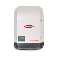
How to handle purge openings for cooling air on Fronius Primo 5.0-1?
- JJennifer RobersonSep 23, 2025
Purge openings for cooling air and the heat sink if necessary.


How to handle purge openings for cooling air on Fronius Primo 5.0-1?
Purge openings for cooling air and the heat sink if necessary.
How to troubleshoot total display failure on Fronius Primo 5.0-1 Inverter?
If the display on your Fronius Inverter has failed completely, check the AC voltage on the inverter connections. It should be 230 V (+10% / -5%).
What to do if Fronius Primo 5.0-1 Inverter shows Overcurrent (AC) error?
The fault should rectify automatically. However, if the Fronius Inverter continuously displays this status code, you should notify a Fronius trained service engineer.
Why is my Fronius Primo 5.0-1 Inverter showing LOW PV OUTPUT?
A 'LOW PV OUTPUT' status code on your Fronius Inverter can be due to the low level of insolation. However, if this code appears when there is sufficient insolation, contact your system engineer.
What causes LOW PV VOLTAGE on Fronius Primo 5.0-1?
The 'LOW PV VOLTAGE' status code on your Fronius Inverter may appear due to the low level of insolation. If this status code occurs when there is sufficient insolation, contact your system engineer.
What happens when DC input voltage MPPT 2 is too high on Fronius Primo 5.0-1?
When the DC input voltage MPPT 2 is too high, the Fronius Inverter resumes with its start-up routine.
What happens when DC input voltage is too low for feeding energy into the grid on Fronius Primo 5.0-1?
When the DC input voltage is too low for feeding energy into the grid, the Fronius Inverter resumes with its start-up routine.
What happens when DC input voltage MPPT 1 is too high on Fronius Primo 5.0-1?
When the DC input voltage MPPT 1 is too high, the Fronius Inverter resumes with its start-up routine.
What happens when AC frequency is too high on Fronius Primo 5.0-1 Inverter?
If the AC frequency is too high, the Fronius Inverter will resume feeding energy into the grid.
What happens when AC voltage is too high on Fronius Inverter?
If the AC voltage is too high, the Fronius Inverter will resume feeding energy into the grid.
| Quantity per pack | 1 pc(s) |
|---|---|
| Purpose | Solar panel |
| Efficiency | 96.9 % |
| Output power | - W |
| Certification | UL 1741-2010 Second Edition (incl. UL1741 Supplement SA 2016-09 for California Rule 21 and Hawaiian Electric Code Rule 14H), UL1998 (for functions: AFCI, RCMU and isolation monitoring), IEEE 1547-2003, IEEE 1547.1-2003, ANSI/IEEE C62.41, FCC Part 15 A & B, NEC 2017 Article 690, C22. 2 No. 107.1-16, UL1699B Issue 2 -2013, CSA TIL M-07 Issue 1 – 2013 |
| Input voltage | 80 - 600 V |
| Output current | 30 A |
| Output voltage | 240 V |
| Input frequency | 45 - 66 Hz |
| Output frequency | 60 Hz |
| Power supply type | Universal |
| Maximum input voltage | 600 V |
| Output power capacity | 5 kVA |
| Adjustable output voltage | - |
| Smartphone remote support | Yes |
| Product color | Black, Grey |
| Depth | 206 mm |
|---|---|
| Width | 429 mm |
| Height | 627 mm |
| Weight | 21500 g |



 Loading...