77
EN
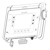
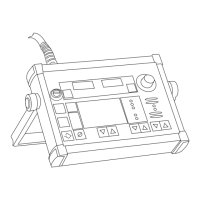
Description of
US control panel
(1)(24)
(23)
(19)
(18)
(16)
(15)
(14)
(13)
(12)(11)
(9)(8) (3)(2)
(19)
(22)
(21) (20)
(7) (6)
(5)
(4)
Fig.3 Control panel for USA
(1) Adjusting dial ... for altering parameters. If the indicator next to the adjusting dial is
lit up, then the selected parameter is one that can be altered.
(2) Parameter selection button ... for selecting the following parameters:
- sheet thickness
- welding current
- wire speed
- indicator F1
- Wirefeed-drive current input
If the indicator is lit up on the parameter selection button and on the adjusting dial,
then the indicated / selected parameter can be altered with the adjusting dial.
(3) Parameter selection button ... for selecting the following parameters:
- arc-length correction
- droplet-detachment / arc-force (dynamic) correction
- welding voltage
- job n°
- indicator F3
If the indicator is lit up on the parameter selection button and on the adjusting dial,
then the indicated / selected parameter can be altered with the adjusting dial.
Warning! Operating the unit incorrectly can cause serious injury and damage.
Do not use the functions described here until you have read and completely
understood the whole of the “Operating Instructions” manuals for the remote-
control units, the wirefeeders and the welding power source.
 Loading...