i
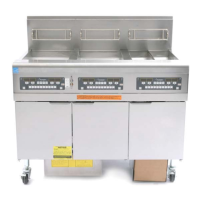
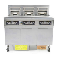
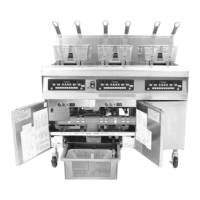
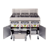
BIGLA30 SERIES LOV™ GAS FRYERS
SERVICE MANUAL
TABLE OF CONTENTS
CHAPTER 1: Service Procedures
1.1 Functional Description ................................................................................................................................... 1-1
1.2 The Electronic Ignition System ...................................................................................................................... 1-1
1.3 Interface Board............................................................................................................................................... 1-2
1.4 Thermostats .................................................................................................................................................... 1-4
1.5 Accessing Fryers for Servicing ...................................................................................................................... 1-4
1.6 Cleaning the Gas Valve Vent Tube ................................................................................................................ 1-4
1.7 Checking the Burner Manifold Gas Pressure ................................................................................................. 1-5
1.8 Measuring Flame Current .............................................................................................................................. 1-7
1.9 Replacing Fryer Components ......................................................................................................................... 1-7
1.9.1 Replacing the Computer or the Computer Wiring Harness .......................................................... 1-7
1.9.2 Replacing the Temperature Probe or High-Limit Thermostat ...................................................... 1-8
1.9.3 Replacing the Interface Board ...................................................................................................... 1-8
1.9.4 Replacing an Ignition Module ...................................................................................................... 1-8
1.9.5 Replacing an Ignitor Assembly .................................................................................................... 1-9
1.9.6 Replacing or Cleaning a Combustion Air Blower ........................................................................ 1-9
1.9.7 Adjusting the Air/Gas Mixture ................................................................................................... 1-10
1.9.8 Replacing a Gas Valve ............................................................................................................... 1-11
1.9.9 Replacing a Burner Assembly .................................................................................................... 1-12
1.9.10 Replacing the Filter Motor, Filter Pump, or Filter Pump ........................................................... 1-13
1.9.11 Replacing the Frypot .................................................................................................................. 1-13
1.9.12 Replacing Frypot Insulation and/or Upper Burner Rails ............................................................ 1-14
1.10 Troubleshooting and Problem Isolation .......................................................................................................... 1-17
1.10.1 Heating (Ignition) Failure .......................................................................................................... 1-18
1.10.2 Improper Burner Function .......................................................................................................... 1-18
1.10.3 Improper Temperature Control .................................................................................................. 1-20
1.10.4 Computer Malfunctions ............................................................................................................. 1-20
1.10.5 Filtration Malfunctions............................................................................................................... 1-20
1.10.6 Leakage ...................................................................................................................................... 1-21
1.11 Troubleshooting Guides ............................................................................................................................... 1-21
1.11.1 Troubleshooting the 24 VAC Circuit ......................................................................................... 1-21
1.11.2 Troubleshooting the Gas Valve .................................................................................................. 1-23
1.11.3 Troubleshooting the Temperature Probe .................................................................................... 1-24
1.11.4 Replacing the Transformer or Filter Relay .............................................................................
.... 1-24
1.12 Probe Resistance Chart ................................................................................................................................ 1-25
1.13 ATO (Automatic Top-Off ) Service Procedures .......................................................................................... 1-25
1.13.1 ATO (Automatic Top-Off Troubleshooting) ............................................................................. 1-25
1.13.2 ATO (Automatic Top-Off Troubleshooting) Board Pins and Positions ..................................... 1-27
1.13.3 Replacing the ATO Board or Transformer ................................................................................. 1-28
1.13.4 Replacing the ATO Pump or Solenoid ....................................................................................... 1-28
1.14 MIB (Manual Interface Board) Service Procedures ..................................................................................... 1-28
1.14.1 Manually Draining, Refilling or Filtering Using the MIB Board ............................................... 1-29
1.14.2 MIB (Manual Interface Board) Troubleshooting ....................................................................... 1-30
1.14.3 MIB (Manual Interface Board) Pin Positions and Harnesses ..................................................... 1-32
1.14.4 MIB (Manual Interface Board) Display Characters ................................................................... 1-33
1.14.5 Replacing the MIB Board .......................................................................................................... 1-33
1.14.6 Control Power Reset Switch ...................................................................................................... 1-33
1.15 RTI Service Issues ....................................................................................................................................... 1-34
1.15.1 RTI MIB Tests ........................................................................................................................... 1-34
1.15.2 RTI LOV™ Wiring with RTI Switchbox .................................................................................. 1-35
1.15.3 RTI Plumbing Schematic ........................................................................................................... 1-35
1.15.4 RTI LOV™ Test Quick Reference ............................................................................................ 1-36
1.16 AIF (Automatic Intermittent Filtration) Service Procedures ........................................................................ 1-38
1.16.1 AIF (Automatic Intermittent Filtration) Troubleshooting .......................................................... 1-38
1.16.2 AIF (Automatic Intermittent Filtration) Actuator Board Pin Positions ...................................... 1-39
 Loading...