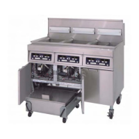
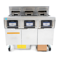
1-2
1.3 Interface Board
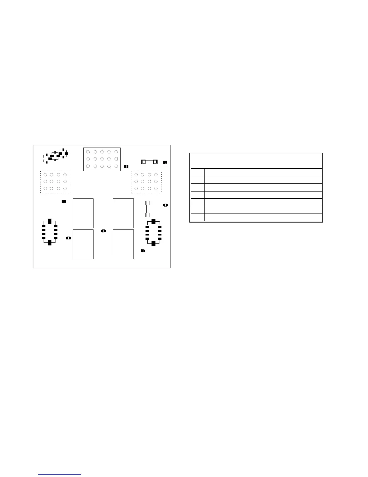
All fryers in this series have an interface board located in the component box behind the control panel. The
interface board provides a link between the computer and the fryer’s individual components without requiring
excessive wiring, and allows the computer to execute commands from one central point.
K2 and K3 are double-pole-double throw (DPDT) relays that supply 24VAC to the ignition and gas valve
circuits, as well as 120VAC to the blower motor. The relays on this board plug into sockets. If a relay fails,
that relay can be replaced. K1 and K4 are single-pole-double throw (SPDT) relays that supply voltage to the
oil level relay sensors and relay board.
LEDs (labeled D1 through D7) are arrayed around the board to assist in troubleshooting.
K4
K1
SOUND
GND
V2D
PWR
AD
AS
V2S
GND
GV
PWR
12V
AIR
24V
PWR
GND
V1D
PWR
ALR
V1S
GV
GND
J2
SMT INTERFACE BOARD KIT 826-2264 (106-6706)
J3
3 6 9 12
2 5 8 11
1 4 7 10
J1
3 6 9 12
2 5 8 11
1 4 7 10
15
12963
14
11852
13
10741
K2 K3
HEAT
RELAY
AND
BLOWER
MOTOR
RELAY
D1
D2
D3
D4
D6
D7
D5
HEAT
RELAY
AND
BLOWER
MOTOR
RELAY
F2 Ignition
3 AMP Module
J6
J7
J8
GND
GND
1
2
3
F1
Blower
Motor
3 AMP
OIL LEVEL
SENSOR
RELAY
OIL LEVEL
SENSOR
RELAY
D1
24 VAC to left gas valve (dual vat only)
D2
24 VAC to left ignition module (dual vat or CE)
D3
24 VAC from transformer
D4
24 VAC to right ignition module
D5
24 VAC to gas valve (right valve if dual vat)
D6
12 VAC from transformer
D7
CE and Japanese units only: air switch closed
INTERFACE BOARD
LED DIAGNOSTIC LIGHTS
NOTE: In full-vat fryers, the relay for the left side (K2) may not be present.
The chart on the following page illustrates current flow through the board, and the table at the top of page 1-4
identifies frequently used test points.
NOTE: Refer to Section 1.11.1 on
page 1-22 for troubleshooting
flowchart.
 Loading...