Innovation · Expertise · Agility
12
Hardware Installation and Parts Replacement
Switch Hardware Installation and Maintenance Guide
Procedure
1. Wear an anti-static wristband or anti-static gloves. If you wear an anti-static wristband, ensure that
one end of the wristband is grounded and the other end has contact with your skin.
2. Turn off the power module and the external power supply system for the switch.
3. Connect the power cable to the power module.
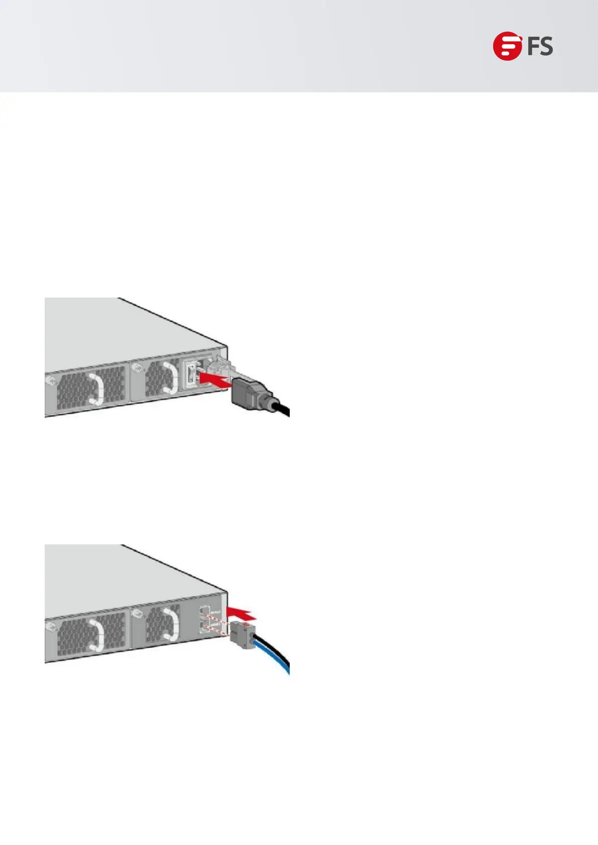
Perform the following steps to connect the AC power cable:
Insert the plug of the AC power cable into the power socket in the AC power module.
Figure 7: Connect the AC Power Cable
Connect the other end of the AC power cable to the external AC power supply system.
Perform the following steps to connect the DC power cables:
Insert the DC power cable plug to the power socket in the DC power module. Ensure that the positive
pole of the plug is connected to the positive socket and the negative pole is connected to the negative
socket on the power module.
Figure 8: Connect the DC Power Cable
Connect the other end of the DC power cable with a cold-pressed terminal to the external DC power supply system.
Ensure that the polarity is consistent with the equipment end.
1.5.3 Connecting Ethernet Cables
Connect the RJ45 connector of an Ethernet cable to the management port on the equipment, and the other
end to a network management switch or terminal.

 Loading...