Innovation · Expertise · Agility
14
1.5.6 Connecting the Console Port
1.6.1 Verifying Cabinet
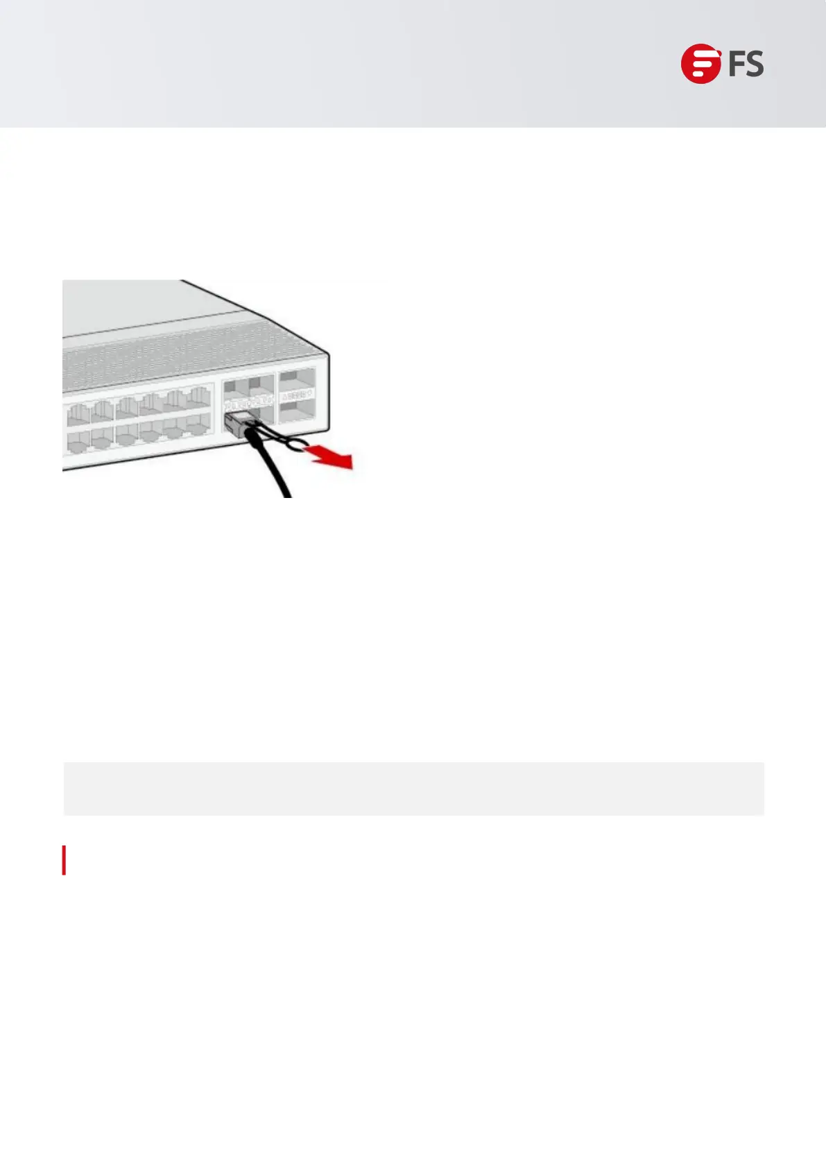
When disassembling, first gently push the cable connector inwards, then hold the pull ring and pull it
outwards. Do not directly pull the cable by gripping the cable connector. Refer to Figure 10 for reference.
• External power supply matches the distribution panel of the cabinet.
• The front and back doors can be closed after the switch is installed in the cabinet.
• The cabinet and all cables are securely fastened.
• The switch has been installed in the cabinet.
• Maintain a minimum clearance of 200mm (7.87 in.) around the switch for air circulation.
Hardware Installation and Parts Replacement
Switch Hardware Installation and Maintenance Guide
Figure 10: Removing a High-speed Cable
8. Cable bundling: Arrange the connected high-speed cables neatly without crossing each other. Every
150mm to 300mm, use cable ties to secure them, and trim off any excess portion of the cable ties using
diagonal cutting pliers.
9. Replace all temporary labels with official high-speed cable labels.
Steps
Connect the RJ45 connector of an Ethernet cable to the console port of the switch, and connect the
DB9 connector to a network management switch or terminal.
• By default, the baud rate is 9600, data bit 8, parity check none, stop bit 1, and flow control none.
1.6 Post-Installation Checks

 Loading...