Innovation · Expertise · Agility
20
Hardware Installation and Parts Replacement
Switch Hardware Installation and Maintenance Guide
2. Before replacing an optical module, determine in which cabinet and chassis the optical module is
installed, find the optical module in the chassis, and attach a label to the optical module. Record optical
fiber locations on the optical module to be replaced and check whether the labels on the optical fibers
are correct and clear. If any label is unclear, make and attach a new label to the optical fiber to ensure
correct connection.
3. Rotate the handle of the optical module down, gently push the optical module, and then pull out the
optical module with the handle. Remove the optical fibers from the optical module and cover them with
dust caps.
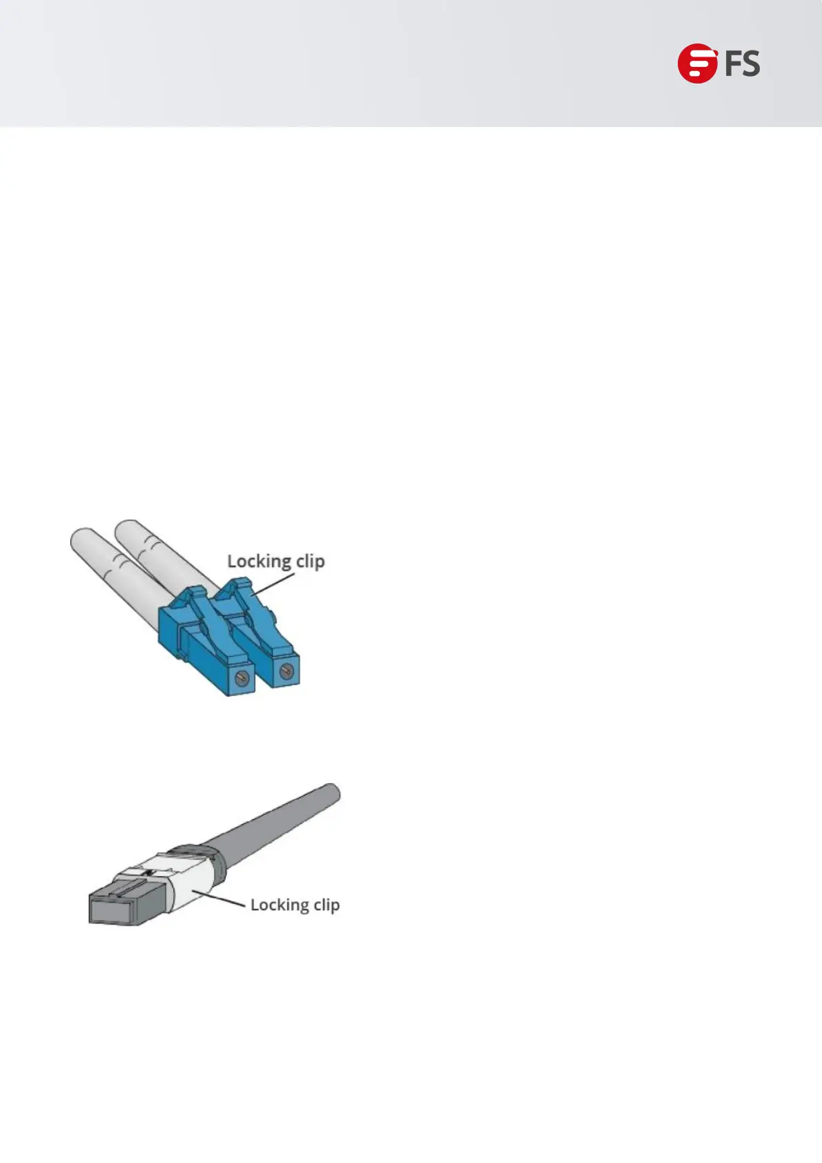
Two types of latches on fiber optic connectors:
• LC/PC connector,opened by pressing the buckle, as shown in Figure 14.
• MPO connector,opening automatically when the buckle is pulled, as shown in Figure 15.
Figure 14: LC/PC Connector
Figure 15: MPO Connector
4. Pull out the optical module, plug the dustproof plug and dispose of it.

 Loading...