EasyManua.ls Logo

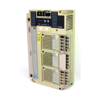
Fuji Electric MICREX-F Series User Manual

Fuji Electric MICREX-F Series
48 pages
To Next Page IconTo Next Page
Page #1 background imageLoading...
Page #1 background image
1
Fuji Electric Co.,Ltd.
MICREX-F Series
SIO Driver
1 System Configuration.......................................................................................................3
2 Selection of External Device ............................................................................................7
3 Example of Communication Setting.................................................................................8
4 Setup Items....................................................................................................................24
5 Cable Diagram ...............................................................................................................29
6 Supported Device...........................................................................................................44
7 Device Code and Address Code....................................................................................46
8 Error Messages..............................................................................................................47
Question and Answer IconNeed help?

Do you have a question about the Fuji Electric MICREX-F Series and is the answer not in the manual?

Fuji Electric MICREX-F Series Specifications

General IconGeneral
Protection ClassIP20
SeriesMICREX-F
Programming LanguageFunction Block Diagram, Instruction List, Sequential Function Chart
Communication InterfaceEthernet, RS-232, RS-485
Input Voltage100-240V AC or 24V DC
Output TypeRelay, Transistor
Memory CapacityVaries depending on model
Operating Temperature0°C to 55°C
TypeProgrammable Logic Controller (PLC)

Summary

System Configuration

Connection Configuration

Details RS232C and RS422/485 connection configurations and diagrams.

Selection of External Device

Setup Items

Lists and explains setup parameters for connecting an External Device via GP-Pro EX.

Example of Communication Setting

Setting Example 1

Demonstrates GP-Pro EX communication settings for the first example.

Setting Example 2

Presents GP-Pro EX communication settings for the second example.

Setting Example 3

Shows GP-Pro EX communication settings for the third example.

Setting Example 4

Details GP-Pro EX communication settings for the fourth example.

Setting Example 5

Illustrates GP-Pro EX communication settings for the fifth example.

Setting Example 6

Provides GP-Pro EX communication settings for the sixth example.

Setting Example 7

Offers GP-Pro EX communication settings for the seventh example.

Setup Items

Setup Items in GP-Pro EX

Explains communication parameters for GP-Pro EX setup on the Display.

Setup Items in Offline Mode

Details communication settings for the Display's offline mode configuration.

Cable Diagram

Cable Diagram 1

Shows the first set of diagrams for connecting cables between devices.

Cable Diagram 2

Presents the second set of diagrams for connecting cables between devices.
Cable Diagram 3

Illustrates the third set of diagrams for connecting cables between devices.
Cable Diagram 4

Details the fourth set of diagrams for connecting cables between devices.
Supported Device

Device Code and Address Code

Error Messages

Related product manuals