Do you have a question about the Fuji Electric PXG9 and is the answer not in the manual?
| Communication | RS-485 (Modbus RTU) |
|---|---|
| Control Method | PID control |
| Input Type | Thermocouple, RTD, DC Voltage, DC Current |
| Output Type | Relay, voltage, current |
| Power Supply | 100 to 240 VAC, 50/60 Hz or 24 VAC/VDC |
| Accuracy | ±0.3% of full scale |
| Operating Humidity | 35 to 85% RH (non-condensing) |
Specifies ambient temperature and humidity for intended use.
Details required spacing for safe installation.
Defines insulation classes for safety.
Indicates serious consequences from mishandling.
Indicates potential harm from mishandling.
Highlights need for fail-safe in life-critical uses.
Forbids use in applications directly involving human lives.
Recommends regular checks for continued safe operation.
States the standard warranty duration.
Guides on attaching packing for waterproof integrity.
Advises on correct torque to prevent damage.
Covers compensation leads and noise separation.
Suggests insulation transducers and noise filters.
Notes on output relay life and external protection.
Advises checking the delivered model against the order.
Points to sections for installation details.
Points to sections for wiring diagrams.
Instructions for turning on the unit.
Guides to sections on unit operation.
Points to sections for advanced features.
Guides to sections on error handling.
Advises waiting for thermal stabilization before measurements.
Provides dimensions for unit and panel cutouts.
Explains how to use mounting fixtures.
Details packing placement for waterproofing.
Advises on keeping sides unobstructed for cooling.
Notes on ambient temperature and spacing for close mounting.
Provides advice on terminal screw size and torque.
Shows wiring for standard model.
Shows wiring for motorized valve model.
Important notes regarding wiring connections.
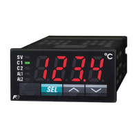
Identifies and explains unit components and indicators.
Describes monitor mode and its displays.
Explains mode switching and basic key functions.
Covers changing SV, MV, and other operational modes.
Step-by-step instructions for setting parameters.
Procedures for setting and using passwords.
Lists and explains parameters for operation control.
Lists and explains parameters for PID control.
Describes saving PV and PID values.
Details creating temperature patterns.
Parameters for controlling output limits.
Parameters for setting input limits.
Lists parameters for monitoring various statuses.
Parameters for configuring input/output ranges.
Parameters for DI/DO, LEDs, and other controls.
Configures alarm detection conditions.
Sets parameters for host communication.
Parameters for valve control using PFB.
Procedures for setting user passwords.
How to hide specific parameters from display.
Basic ON/OFF control method.
Explains PID control principles.
PID control with reduced overshoot.
Automatic PID calculation for changing conditions.
PID control for overshoot suppression on power cycle.
Steps to automatically set PID parameters.
Explains servo and PFB valve control methods.
How to set the valve stroke time for servo control.
Detailed valve control using position feedback.
How to manually set control output.
Setting up temperature patterns with steps.
Assigning functions to digital inputs.
Configuring digital outputs for events and alarms.
Setting delay and hysteresis for alarms.
Using analog input as the set value (SV).
Detecting heater burnout via CT.
Detecting control loop open circuits.
Detecting load short circuits via CT.
Introduces additional functions like soft start.
Suppressing MV output during startup.
Halting control and maintaining output on error.
Setting outputs for standby mode.
Smoothly changing SV based on slope.
Switching between multiple SV settings.
Switching PID parameters using palette or user key.
Configuring controller startup mode (Auto/Manual).
Assigning functions to the user key.
Setting sensor type, range, and decimal point.
Configuring control output range (current/voltage).
Setting normal or reverse control operation.
Lists error codes and possible causes.
Table of input types, ranges, and codes.
Codes for alarm types and action diagrams.
Codes for dual set value alarms.
Lists model numbers and their specifications.
Details the meaning of each digit in the model number.
Codes for timer functions assigned to DO.
Details power requirements and consumption.
Electrical ratings for control outputs.
Input accuracy and resolution details.
Specifications for digital outputs and inputs.
Details for communication interfaces.
Environmental requirements for operation and storage.