En-11
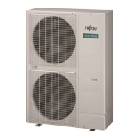
6.6.2 External input terminal
Setting to low noise mode, cooling priority/heating priority selection, outdoor unit operation
peak control setting, emergency/batch stop and electricity meter pulse are possible from
the outside.
When connecting cable to Input 2
Cable (for external
input and output)
Cable tie (tightened with
transmission cable)
Cable (for external input and output)
* If the outdoor unit is not installed in the wall, cover
the exposed part of cable with a 1 mm thick or more
insulation
tubing.
About 21-5/8 in (550 mm)
Wiring method and specifications
* A twisted pair cable (22 AWG (0.33 mm²)) should be used. Maximum length of cable is
492 ft (150 m).
* Use an external input and output cable with appropriate external dimension, depending
on the number of cables to be installed
* For each input, pin No. 1 is of positive polarity and pin No. 2 is of ground level.
Connected unit Connected unit
Connected unit Connected unit Connected unit
Input1
CN131
(Yellow)
Input2
CN132
(Green)
Input3
CN133
(White)
Input4
CN134
(Red)
Input5
CN135
(Orange)
P.C.B
Operation behavior
Each input terminal works as follows.
Connector Input signal Status
Input1
CN131 (Yellow)
OFF Normal operation
ON Low noise mode operation
Input2
CN132 (Green) *1
OFF Cooling priority
ON Heating priority
Input3
CN133 (White)
OFF Normal operation
ON Outdoor unit operation peak control
Input4
CN134 (Red)
OFF Normal operation
ON Batch stop or Emergency stop operation (*2)(*3)
Input5
CN135 (Orange)
(*4)
No pulse No information from electricity meter
Pulse Power usage information from electricity meter
The operations of each input terminal and the selection of function are set with the push
button on the PC board of outdoor unit. About the setting, please refer to “7.4. Push button
setting”.
NOTE:
*1: The “external input priority mode” must be set by pressing push button on PC board
of outdoor unit. (Refer to “7. FIELD SETTING”.)
*2: Batch stop or Emergency stop pattern can be selected by outdoor unit PC board
push button. (Refer to “7. FIELD SETTING”.)
*3: The emergency stop function mounted in this product does not guarantee the regu-
lations of each country. For this reason, sufficient checking is necessary regarding
use.
Especially, since the fact that the equipment may not be emergency-stopped in the
case of breaking of the wiring to the external input terminals and communication
line, communication error due to noise, VRF external input circuit trouble, etc. must
be considered, the provision of double measures that add direct interruption of the
power supply by switch, etc. is recommended as a precaution.
*4: Pulse input to CN135 must be width 50 ms or more, and must be interval 50 ms or
more.
6.6.3 External output terminal
You can detect the operation condition of outdoor unit and the abnormal situation of both
indoor and outdoor unit.
Wiring method and specifications
Error status
This output indicates the outdoor unit
and connected indoor unit's “Normal” or
“Error” status.
Operation status
This output indicates the outdoor unit's
“Operation” status.
Connector
Output
voltage
Status
Output1
CN136
(Black)
0V Normal
DC 12-24 V
(*5)
Error
Output2
CN137
(Blue)
0V Stop
DC 12-24 V
(*5)
Operation
P.C.B
CN136 (Black) or
CN137 (Blue)
DC power supply
(External) 12-24 V
Connected load (Operation Indica-
tor or Error Indicator)
Connected unit
*5: Provide a DC 12 to 24 V power supply.
Select a power supply capacity with an ample surplus for the connected load.
*6: The allowable current is 30 mA or less.
Provide a load resistance such that the current becomes 30 mA or less.
*7: Polarity is [+] for pin 1 and [-] for pin 2. Connect correctly.
Do not impress a voltage exceeding 24 V across pins 1-2.
* A twisted pair cable (22 AWG (0.33 mm²)) should be used. Maximum length of cable is
492 ft (150 m).
* Use an external input and output cable with appropriate external dimension, depending
on the number of cables to be installed.
7. FIELD SETTING
CAUTION
Discharge the static electricity from your body before setting up the DIP switches.
Never touch the terminals or the patterns on the parts that are mounted on the PC
board.
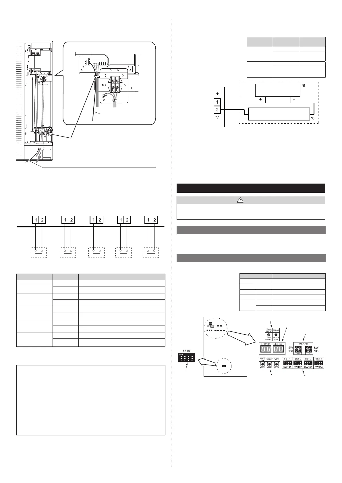
7.1. Field setting switches
Remove the service panel of the outdoor unit and the cover of the electrical component
box to access the PC board of the outdoor unit.
PC board switches for various settings and LED displays are shown in the figure.
7.2. DIP switch setting
7.2.1 List of Settings
SET 5 must be set for the DIP
switch.
Configure the settings before turn-
ing on the power. Settings for SET
1, SET 2, SET 3 and SET 4 DIP
switches are factory default ones. Do
not change them.
DIP Switch Function
SET 1 1-4 Prohibited
SET 2 1-4 Prohibited
SET 3 1-4 Prohibited
SET 4 1-4 Prohibited
SET 5
1-3 Prohibited
4 Terminal resistor setting
7-segment display
Push button
LED lamp
Rotary switch
Outdoor unit printed circuit board
DIP switch
DIP switch
9380545361-02_3L.indb 119380545361-02_3L.indb 11 2022/10/26 14:59:372022/10/26 14:59:37
 Loading...