En-7
CAUTION
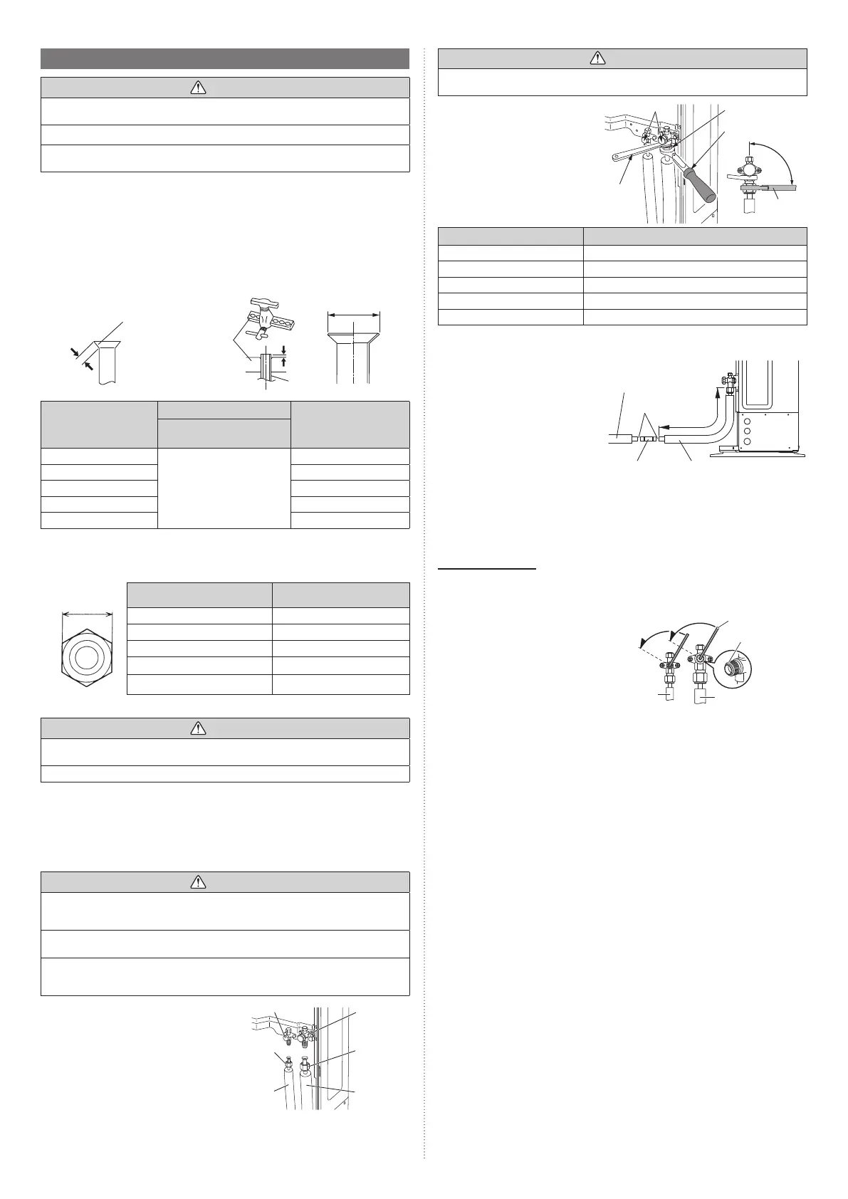
Hold the torque wrench at its grip, keeping it in a right angle with the pipe, in order to
tighten the flare nut correctly.
Outer panel may be distorted if
fastened only with a wrench. Be
sure to fix the elementary part with a
holding wrench (spanner) and fasten
with a torque wrench (refer to below
diagram). Do not apply force to the
blank cap of the valve or hang a
wrench, etc., on the cap. If blank cap
is broken, it may cause leakage of
refrigerant.
Blank cap
Flare nut
90°
Torque wrench
Holding
wrench
Torque
wrench
Flare nut [in (mm)] Tightening torque [lbf·ft (N·m)]
1/4 (6.35) dia. 11.8 to 13.3 (16 to 18)
3/8 (9.52) dia. 23.6 to 31.0 (32 to 42)
1/2 (12.70) dia. 36.1 to 45.0 (49 to 61)
5/8 (15.88) dia. 46.5 to 55.3 (63 to 75)
3/4 (19.05) dia. 66.4 to 81.1 (90 to 110)
In the case of AOU60RLAVM4
It is necessary to change a connection
pipe diameter by using Reducer.
(1) Reducer must be brazed in the
outside of the outdoor unit.
(2) Distance between 3-way valve and
reducer ≤ 3 ft (1 m)
(3) The part of Reducer do insulation
processing after brazing.
Example: Case of front connection
Connection pipe (Gas)
(Pipe outside dia.: 3/4 in
(19.05 mm))
Brazing
3 ft (1 m)
or less
Reducer
(accessory)
Connection pipe (Gas)
(Pipe outside dia.: 5/8 in
(15.88 mm))
5.4.4 Handling precautions for the valves
• Mounted part of Blank cap is sealed for protection.
• Fasten blank cap tightly after opening valves.
Operating the valves
• Use a hexagon wrench (size 3/16 in (4 mm)).
Opening:
(1) Insert the hexagon wrench into the
valve shaft, and turn it counterclock-
wise.
(2) Stop turning when the valve shaft can
no longer be turned. (Open position)
Opening
direction
Hexagon wrench
Seal
(blank cap
installation
portion)
Liquid
pipe
Gas pipe
Opening
direction
Closing:
(1) Insert the hexagon wrench into the
valve shaft, and turn it clockwise.
(2) Stop turning when the valve shaft can
no longer be turned. (Closed position)
5.4. Pipe connection
CAUTION
Do not use mineral oil on a flared part. Prevent mineral oil from getting into the system
as this would reduce the lifetime of the units.
While brazing the pipes, be sure to blow dry nitrogen gas through them.
The maximum lengths of this product are shown in the table. If the units are further
apart than this, correct operation cannot be guaranteed.
5.4.1 Flaring
• Use special pipe cutter and fl are tool exclusive for R410A.
(1) Cut the connection pipe to the necessary length with a pipe cutter.
(2) Hold the pipe downward so that the cuttings will not enter the pipe and remove any
burrs.
(3) Insert the flare nut (always use the flare nut attached to the indoor and outdoor units
respectively) onto the pipe and perform the flare processing with a flare tool. Leakage
of refrigerant may result if other flare nuts are used.
(4) Protect the pipes by pinching them or with tape to prevent dust, dirt, or water from
entering the pipes.
B
A
L
Check if [L] is flared uniformly and
is not cracked or scratched.
Pipe
Die
Pipe outside diameter
[in (mm)]
Dimension A [in (mm)]
Dimension B
0 (0)
-0.015 (-0.4)
[in (mm)]
Flare tool for R410A, clutch
type
1/4 (6.35)
0 to 0.020
(0 to 0.5)
3/8 (9.1)
3/8 (9.52) 1/2 (13.2)
1/2 (12.70) 5/8 (16.6)
5/8 (15.88) 3/4 (19.7)
3/4 (19.05) 15/16 (24.0)
When using conventional (R22) fl are tools to fl are R410A pipes, the dimension A should
be approximately 0.020 in (0.5 mm) more than indicated in the table (for fl aring with R410A
fl are tools) to achieve the specifi ed fl aring. Use a thickness gauge to measure the dimension
A. It is recommended that a R410A fl aring tool is used.
Width across
fl ats
Pipe outside diameter
[in (mm)]
Width across flats of Flare
nut [in (mm)]
1/4 (6.35) 11/16 (17)
3/8 (9.52) 7/8 (22)
1/2 (12.70) 1 (26)
5/8 (15.88) 1-1/8 (29)
3/4 (19.05) 1-7/16 (36)
5.4.2 Bending pipes
CAUTION
To prevent breaking of the pipe, avoid sharp bends. Bend the pipe with a radius of
curvature of 4 in (100 mm) or more.
If the pipe is bent repeatedly at the same place, it will break.
• If pipes are shaped by hand, be careful not to collapse them.
• Do not bend the pipes at an angle of more than 90°.
• When pipes are repeatedly bent or stretched, the material will harden, making it difficult
to bend or stretch them anymore.
• Do not bend or stretch the pipes more than 3 times.
5.4.3 Pipe connection
CAUTION
Be sure to install the pipe against the port on the indoor unit and the outdoor unit cor-
rectly. If the centering is improper, the flare nut cannot be tightened smoothly.
If the flare nut is forced to turn, the threads will be damaged.
Do not remove the flare nut from the outdoor unit pipe until immediately before connect-
ing the connection pipe.
After installing the piping, make sure that the connection pipes do not touch the com-
pressor or outer panel. If the pipes touch the compressor or outer panel, they will vibrate
and produce noise.
(1) Detach the caps and plugs from the
pipes.
(2) Center the pipe against the port on the
outdoor unit, and then turn the flare nut
by hand.
(3) Tighten the flare nut of the connec-
tion pipe at the outdoor unit valve
connector.
(4) After tightening the flare nut by hand,
use a torque wrench to fully tighten it.
3-way valve (Liquid)
3-way
valve (Gas)
Connection
pipe (Liquid)
Flare nut
Connection
pipe (Gas)
Flare nut
9380545361-02_3L.indb 79380545361-02_3L.indb 7 2022/10/26 14:59:362022/10/26 14:59:36
 Loading...