En-4
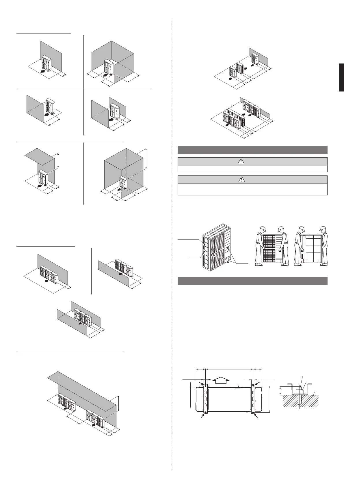
3.2.1 Single outdoor unit installation
When the upward area is open Unit: in (mm)
(1) Obstacles at rear only
6 (150)
(2) Obstacles at rear and sides only
8 (200)
12 (300)
8 (200)
(3) Obstacles at front only
40 (1000)
or more
(4) Obstacles at front and rear only
40 (1000) or
more
6 (150)
When an obstruction is present also in the upward area
Unit: in (mm)
(1) Obstacles at rear and above only
12 (300)
Max. 19 (500)
40 (1000)
(2) Obstacles at rear, sides, and above only
60
(1500)
10 (250)
10 (250)
20 (500)
Max. 19 (500)
3.2.2 Multiple outdoor unit installation
• Provide at least 4 in (100 mm) of space between the outdoor units if multiple units are
installed.
• When routing the piping from the side of an outdoor unit, provide space for the piping.
When the upward area is open Unit: in (mm)
(1) Obstacles at rear only
12 (300)
(2) Obstacles at front only
60 (1500)
or more
(3) Obstacles at front and rear only
20 (500)
60 (1500) or more
When an obstruction is present also in the upward area Unit: in (mm)
(1) Obstacles at rear and above only
• Up to 3 units can be installed side by side.
• When 4 units or more are arranged in a line, provide the space as shown below.
60 (1500)
20 (500)
Max. 11 (300)
60 (1500)
3.2.3 Outdoor units installation in multi row
Unit: in (mm)
* The following settings are not recommended in case of cooling by a low outside tem-
perature.
(1) Single parallel unit arrangement
6 (150)
24 (600)
40 (1000)
79 (2000) or more
(2) Multiple parallel unit arrangement
20 (500)
24 (600)
60 (1500)
119 (3000) or more
3.3. Transporting the unit
WARNING
Do not touch the fi ns. Otherwise, personal injury could result.
CAUTION
When carrying the unit, hold the handles on the right and left sides and be careful.
If the outdoor unit is carried from the bottom, hands or fi ngers may be pinched.
• Carry slowly in the manner as shown on “Fig. B” holding the handles “Fig. A” in right and
left sides. (Be careful not to touch with hands or objects.)
• Be sure to hold the handles on the sides of the unit. Otherwise, the suction grilles on the
sides of the unit may be deformed.
Front view
Rear view
Fig. B
Handle
Handle
Suction grille
Fig. A
3.4. Installing the unit
• Please install the outdoor unit without slant. (within 3 degrees )
• Install 4 anchor bolts at the locations indicated with arrows in the figure.
• To reduce vibration, do not install the unit directly on the ground. Install it on a secure
base (such as concrete blocks).
• The foundation shall support the legs of the unit and have a width of 1 in (50 mm) or more.
• Depending on the installation conditions, the outdoor unit may spread its vibration during
operation, which may cause noise and vibration. Therefore, attach damping materials
(such as damping pads) to the outdoor unit during installation.
• Install the foundation, making sure that there is enough space for installing the connec-
tion pipes.
• Secure the unit to a solid block using foundation bolts. (Use 4 sets of commercially avail-
able M10 bolts, nuts, and washers.)
• The bolts should protrude 13/16 in (20 mm). (Refer to the figure.)
• If overturning prevention is required, purchase the necessary commercially available
items.
6-9/16
(166)
AIR
25-9/16
(650)
6-1/16
(154)
1-15/16
(50)
1-15/16
(50)
5/8 (16)
13/16 (20)
16-1/8 (410)
Unit: in (mm)
Bolt
Nut
Base
9380545361-02_3L.indb 49380545361-02_3L.indb 4 2022/10/26 14:59:362022/10/26 14:59:36
 Loading...