En-15
8. PIPE INSTALLATION II
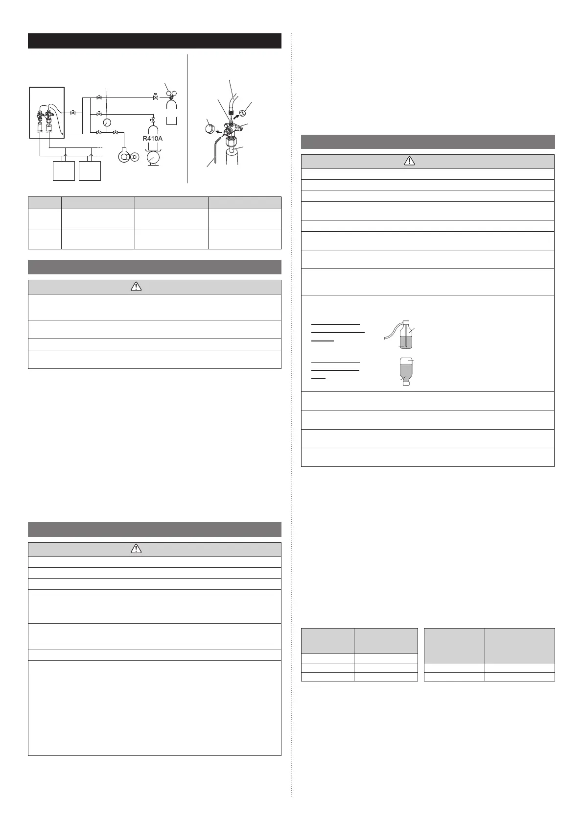
Fig. A Connection system Fig. B
Outdoor unit
Pressure
gauge
Vacuum
pump
Scale
Pressure regu-
lating valve
Nitrogen
Indoor
unit
Indoor
unit
Service hose
with valve core
Charging
port
Charging
port cap
3-way
valve
Connecting
pipe
Blank cap
Hexagon wrench
4 mm (5/32")
Tab le. A
Pipe 3-way valve Blank capCharging port cap
Liquid
valve
5.2 to 6.6 lbf·ft
(7.0 to 9.0 N·m)
14.8 to 18.5 lbf·ft
(20.0 to 25.0 N·m)
9.2 to 11.8 lbf·ft
(12.5 to 16.0 N·m)
Gas
valve
8.1 to 9.6 lbf·ft
(11.0 to 13.0 N·m)
22.1 to 25.8 lbf·ft
(30.0 to 35.0 N·m)
9.2 to 11.8 lbf·ft
(12.5 to 16.0 N·m)
8.1. Sealing test - Pressure (leak) testing
CAUTION
Use only nitrogen gas.
Never use refrigerant gas, oxygen, flammable gas or poisonous gas to pressurize the
system. (If oxygen is used. There is danger of an explosion.)
Do not shock during sealing test.
It can rupture the pipes and cause serious injury.
Do not turn on the power unless all operations are complete.
Do not block the walls and the ceiling until the sealing test and charging of the refriger-
ant gas have been completed.
After connecting the pipes, perform a sealing test.
Recheck that the spindle of the 3-way valve are closed before performing a sealing test.
(Fig. B)
Pour nitrogen gas through both the liquid pipe and the gas pipe.
Pressurize nitrogen gas to 609 psi (4.2 MPa) to perform the sealing test.
Check all flare connection and brazed areas.
Then, check that the pressure has not decreased.
Compare the pressures after pressurizing and letting it stand for 24 hours, and check that
the pressure did not decreased.
* When the outdoor temperature changes 9 degrees F (5 degrees C), the test pressure
changes 7.25 psi (0.05 MPa.).
If the pressure has dropped, the pipe joints may be leaking.
If a leakage is found, immediately repair it and perform a sealing test again.
* Decrease the pressure of nitrogen gas before brazing
After completing the sealing test, release the nitrogen gas from both valves.
Release the nitrogen gas slowly.
8.2. Vacuum process
CAUTION
Do not turn on the power unless all operations are complete.
If the system is not evacuated sufficiently, its performance will drop.
Be sure to evacuate the refrigerant system using a vacuum pump.
The refrigerant pressure may sometimes not rise when a closed valve is opened after
the system is evacuated using a vacuum pump. This is caused by the closure of the
refrigerant system of the outdoor unit by the electronic expansion valve. This will not
affect the operation of the unit.
Use a clean gauge manifold and charging hose that were designed specifically for use
with R410A. Using the same vacuum equipment for different refrigerants may damage
the vacuum pump or the unit.
Do not purge the air with refrigerants, but use a vacuum pump to evacuate the system.
• If moisture enter the piping, follow below. (i.e., if doing work during the rainy season,
if the actual work takes long enough that condensation may form on the inside of the
pipes, if rain might enter the pipes during work, etc.)
• After operating the vacuum pump for 2 hours, pressurize to 7.25 psi (0.05 MPa)
(i.e., vacuum breakdown) with nitrogen gas, then depressurize down to 500 microns
(-100.7 kPa) for an hour using the vacuum pump (vacuum process).
• If the pressure does not reach 500 microns (-100.7 kPa) even after depressur-
izing for at least 2 hours, repeat the vacuum breakdown - vacuum process perform
triple evacuation procedure as necessary to bring the vacuum down to 500 microns
(-100.7 kPa) or lower.
After vacuum process, maintain the vacuum for an hour and make sure the pressure
does not rise by monitoring with a vacuum gauge.
Evacuation procedure
(1) Remove the caps of the gas pipe and liquid pipe and check that the valves are
closed.
(2) Remove the charging cap.
(3) Connect a vacuum pump and a pressure gauge to a charging hose and connect it to
the charging port.
(4) Activate the vacuum pump and vacuum the indoor unit and connection piping until
the pressure gauge becomes 500 microns (-100.7 kPa).
Evacuate from both the gas pipe and the liquid pipe.
(5) Continue evacuating the system for 1 hour after the pressure gauge reads
500 microns (-100.7 kPa).
(6) Remove the charging hose and reinstall the charging cap.
8.3. Additional charging
CAUTION
Do not turn on the power unless all operations are complete.
After evacuating the system, add refrigerant.
Do not charge the system with a refrigerant other than R410A.
Always keep to the limit on the total amount of refrigerant. Exceeding the limit on the
total amount of refrigerant will lead to malfunction during charging of refrigerant.
Do not reuse recovered refrigerant.
Use an electronic scale to measure the charging amount of refrigerant.
Adding more refrigerant than the specified amount will cause a malfunction.
Charge refrigerant using the liquid pipe.
Adding refrigerant through the gas pipe will cause a malfunction.
Add refrigerant by charging the system with the refrigerant in the liquid state. If the re-
frigerant gas cylinder is equipped with a siphon, it is not necessary to place the cylinder
upright.
Check if the steel cylinder has a siphon installed or not before filling. (There is an indica-
tion “with siphon for filling liquid” on the steel cylinder.)
Filling method
for cylinder with
siphon
Liquid
Gas
R410A
Set the cylinder vertical and fill with
the liquid.
(Liquid can be filled without turning
bottom up with the siphon inside.)
Filling method
for other cylin-
ders
Liquid
Gas
R410A
Turn bottom up and fill with liquid.
(Be careful to avoid turning over the
cylinder.)
Be sure to use the special tools for R410A for pressure resistance and to avoid mixing
of impure substances.
If the units are further apart than the maximum pipe length, correct operation cannot be
guaranteed.
Make sure to back closing valve after refrigerant charging. Otherwise, the compressor
may fail.
Minimize refrigerant release to the air. Excessive release is prohibited under the Freon
Collection and Destruction Law.
8.3.1 Procedure for charging the system with refrigerant
(2) Remove the charging port cap from the liquid pipe.
(3) Attach a charging hose to the refrigerant gas cylinder, and connect it to the charging
port.
(4) Add refrigerant by calculating the additional refrigerant volume in accordance with the
calculation formula indicated below.
(5) Remove the charging hose and install the charging port cap.
(6) Remove the blank caps (gas pipe and liquid pipe) and open the valves.
(7) Close the blank caps.
(8) After adding refrigerant, indicate the added charging volume on the unit.
* Tighten the blank caps and charging port caps to the torque values specified in the
Table A. To open and close the valves, use an M4 hexagon wrench.
8.3.2 Checking total amount of refrigerant and calculating the
amount of refrigerant charge to be added
• The amount of refrigerant charge to be added is the total value of the basic refrigerant
charge amount and the value calculated from the length of the liquid pipe.
• Round up the value to 2 decimal places.
Model
“B”
Factory charged
amount [lbs (kg)]
Diameter of liquid
pipe [in (mm)]
“a”
Additional amount
for pipe length [lbs/ft
(kg/m)]
AOU36RLAVM4 10.58 (4.80)
AOU48RLAVM4 11.68 (5.30) Ø 1/4 (6.35) 0.014 (0.021)
AOU60RLAVM4 11.68 (5.30) Ø 3/8 (9.52) 0.039 (0.058)
9380545361-02_3L.indb 159380545361-02_3L.indb 15 2022/10/26 14:59:382022/10/26 14:59:38
 Loading...