En-12
7.2.2 Terminating resistor setting
CAUTION
Be sure to set the terminal resistor according to specifications.
Set the terminal resistor for every network segment (NS).
If terminal resistor is set in multiple devices, the overall communication system may be
damaged.
If terminal resistor is not set in a device, abnormal communication may occur.
• Be sure to set 1 terminal resistor in a network segment. You can set the terminal resistor
at the outdoor unit or Signal amplifier.
• When setting the terminal resistor of a Signal amplifier, refer to the installation manual of
the Signal amplifier.
• When setting multiple terminal resistors, take note of the following items.
(1) How many network segments are there in a VRF system?
(2) Where will you set the terminal resistors in a network segment? (Condition for 1 seg-
ment: Total number of outdoor and indoor units and Signal amplifiers is less than 64,
or the total length of the transmission cable is less than 500 m)
(3) How many outdoor units are connected to 1 refrigerant system?
Configure the setting (DIP switch SET 5)
of the terminal resistor of the outdoor units
as shown below from conditions (1) to (3).
SET 5
Terminal
resistor
Remarks
4
OFF Disable
—
ON Enable (Factory setting)
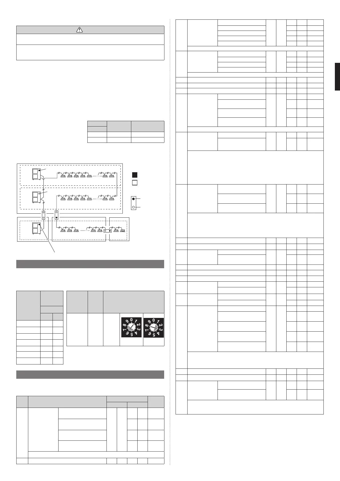
Terminal resistor setting
NS2 (Network
segment 2)
NS3 (Network segment 3)
NS4 (Network
segment 4)
NS1 (Network segment 1)
(Set terminal resistor at outdoor units)
Master unit
Master unit
Master unit
Refrigerant system 1
Refrigerant system 2
Refrigerant system 3
Terminal resistor: off
Terminal resistor: on
Terminal resistor: on
About the setting of
terminal resistor
Outdoor unit
Install
Do not
install
: On
: Off
Signal amplifier
7.3. Rotary switch setting
The rotary switch (REF AD) sets the refrigerant system address of the outdoor unit. Con-
figure the settings only on the master unit of a refrigerant system.
If multiple refrigerant systems are connected, set the rotary switch (REF AD) as shown in
the table below.
Refrigerant
system
address
Rotary
Switch
Setting
Setting
Setting
range
Type of switch
REF AD
×10 ×1
Refrigerant
system
address
0–99
Setting
example
63
000
101
202
303
REF AD × 10
REF AD × 1
⁞⁞⁞
Rotary Switch (REF AD × 1): Factory setting “0”
Rotary Switch (REF AD × 10): Factory setting “0”
98 9 8
99 9 9
7.4. Push button setting
Various functions can be set. Set when necessary.
Perform settings after all indoor units have stopped operation.
Table. A: List of Settings
No Setting Item
7 segment display
Factory
default
First 2 digits Last 2 digits
00
Pipe length setting
(*1)
Standard (131 to 213 ft)
(40 to 65 m)
00
00
z
Short (less than 131 ft)
(less than 40 m)
01
Medium (213 to 295 ft)
(65 to 90 m)
02
Long 1 (295 to 394 ft)
(90 to 120 m)
03
Pipe length means the length between master outdoor unit and the nearest indoor unit.
10
Prohibited (Factory default)
10
00
z
11
Cooling capacity
shift (*1)
Normal mode
11
00
z
Save energy mode
01
High power mode 1 0 2
High power mode 2
03
Prohibited
04
Set this item when necessary.
12
Heating capacity
shift (*1)
Normal mode
12
00
z
Save energy mode
01
High power mode 1
02
High power mode 2
03
Set this item when necessary.
13
Prohibited (Factory default)
13
00
z
14
Prohibited (Factory default)
14
00
z
18 Prohibited (Factory default) 1 8 0 0
z
19
Base pan heater
operating tem-
perature setting
Normal mode
19
00
z
On: 35.6°F (2°C)
Off: 39.2°F (4°C)
01
On: 24.8°F (-4°C)
Off: 28.4°F (-2°C)
02
On: 15.8°F (-9°C)
Off: 19.4°F (-7°C)
03
Normal mode: operating temperature changes according to the operating conditions.
20
Switching between
batch stop or
emergency stop
(*1)
Batch stop
20
00
z
Emergency stop
01
This mode selects the pattern of the stop function to be operated by the external input
terminal (CN134).
• Batch stop: The stop of all indoor units connected to same refrigerant system due to
input signal coming from CN134.
• Emergency stop: When emergency stop is actuated, the indoor unit does not accept
the operation command from the remote controller. On the other hand, when the emer-
gency stop is released (no input from CN134), the air conditioner does not return to the
original operation until the indoor unit is turned on by the remote controller.
21
Operation mode
selecting method
(*1)
Priority given to the first
command
21
00
z
Priority given to external input
of outdoor unit
01
Priority given to administra-
tive indoor unit
02
Select the priority setting of the operation mode.
•
Priority given to the first command: Priority is given to the operation mode which is set first.
• Priority given to external input of outdoor unit: Priority is given to the operation mode
which is set by the external input terminal (CN132).
•
Priority given to administrative indoor unit: Priority is given to the operation mode of the
administrative indoor unit which is set by the wired remote controller.
22
Prohibited (Factory default)
22
00
z
23
Prohibited (Factory default)
23
00
z
24
High static pres-
sure mode
Standard
24
00
z
High static pressure 1
(equivalent to 30 Pa)
01
25
Prohibited (Factory default)
25
00
z
26
Prohibited (Factory default)
26
00
z
27
Prohibited (Factory default)
27
00
z
28
Change of unit
(Temperature)
Celsius (°C)
28
00
z
Fahrenheit (°F) 0 1
29
Change of unit
(Pressure)
Mpa
29
00
z
psi 0 1
30
Energy saving
level setting (*1)
Level 1 (stop)
30
00
z
Level 2
(operated at 40% capacity)
01
Level 3
(operated at 60% capacity)
02
Level 4
(operated at 80% capacity)
03
Level 5
(operated at 100% capacity)
04
The capacity limit can be selected by the external input terminal (CN133) when operat-
ing with the “Energy Saving Peak Cut function”.
The lower the level, the more the effect of energy saving, but the cooling/heating perfor-
mance will also drop.
31
Prohibited (Factory default)
31
00
z
34
Prohibited (Factory default)
34
00
z
35
Presence of
heater selection
control using
outdoor tempera-
ture (*1)
Invalid
35
00
z
Valid
01
If “Heater selection control 1 or 2 using outdoor temperature” is used for any of
the indoor units of the refrigerant system, select "Valid". For more details on set-
tings for this item, see the Design & Technical manual.
9380545361-02_3L.indb 129380545361-02_3L.indb 12 2022/10/26 14:59:372022/10/26 14:59:37
 Loading...