En-6
5. PIPE INSTALLATION
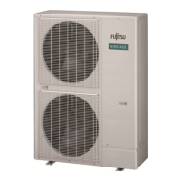
5.1. Brazing
CAUTION
If air or another type of refrigerant enters the
refrigeration cycle, the internal pressure in
the refrigeration cycle will become abnormally
high and prevent the unit from exerting its full
performance.
Pressure regulating valve
Cap
Nitrogen gas
Brazing area
Apply nitrogen gas while brazing the pipes.
Nitrogen gas pressure: 2.9 psi (0.02 MPa)
(= pressure felt sufficiently on the back of
your hand)
If a pipe is brazed without applying nitrogen gas, it will create an oxidation film.
This can degrade performance or damage the parts in the unit (such as the compressor
or valves).
Do not use flux to braze pipes. If the flux is the chlorine type, it will cause the pipes to
corrode.
In additio
n, if the flux contains fluoride, it will affect the refrigerant piping system due to
deterioration of refrigerant oil.
For brazing material, use phosphor copper that does not require flux.
5.2. Indoor unit pipe connections
CAUTION
For details, refer to the Installation Instruction Sheet of each part.
Separation tube
A
B
A
B
B
A
± 15°
GOOD GOOD
Horizontal
Vertical
Horizontal line
or
A:
Outdoor unit or Refrigerant
branch kit
B:
Indoor unit or Refrigerant
branch kit
PROHIBITED
Header
H
1
= 0 to 3/8 in
(0 to 10 mm)
H
2
= 0 to 3/8 in
(0 to 10 mm)
(α
1
: 0° to 1°)
β
1
: -10° to 10°
(α
2
: 0° to 1°)
β
2
: -10° to 10°
C
H
1
α
1
β
1
D
H
2
α
2
β2
GOOD
GOOD
Horizontal line
Horizontal line
View D
View C
Horizontal line
Vertical line
Gas pipe
Liquid pipe
Outdoor
unit side
Outdoor
unit side
PROHIBITED
CAUTION
Do not connect a separation tube after a header.
Leave the distance 2 ft (0.5 m) or more for straight part to branch tube and header.
To indoor unit
To indoor unit
To indoor unit
Main pipe
Main pipe
2 ft (0.5 m) or more
2 ft (0.5 m) or more
To indoor unit
Separation tube
Header
To indoor unit
2 ft (0.5 m) or more
2 ft (0.5 m) or more
To indoor unit
Separation tube
Header
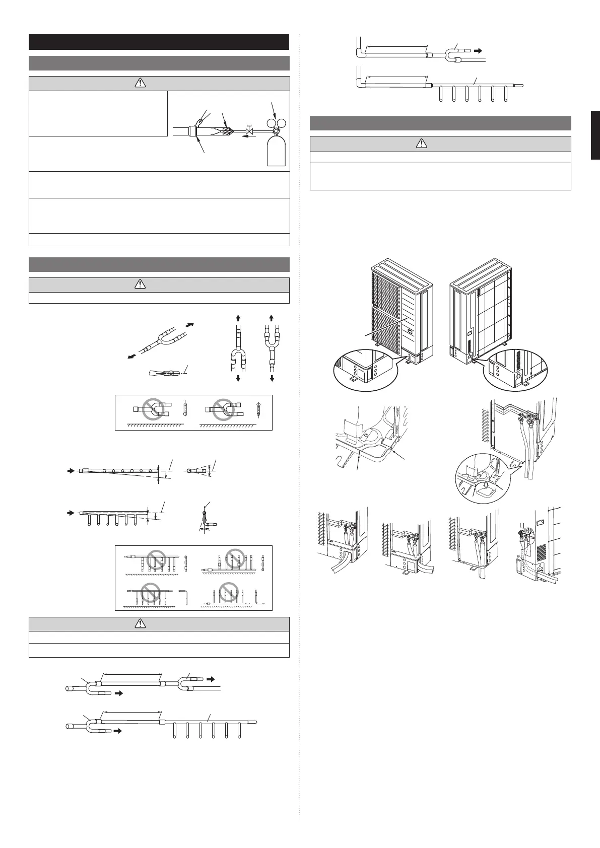
5.3. Opening the knockout hole
CAUTION
Be careful not to deform or scratch the panel while opening the knockout holes.
To protect the piping insulation after opening a knockout hole, remove any burrs from
the edge of the hole. It is recommended to apply rust prevention paint to the edge of the
hole.
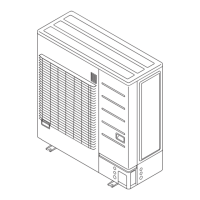
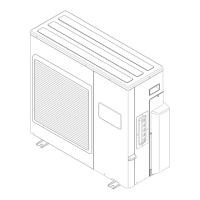
• Pipes can be connected from 4 directions, front, lateral side, rear side and bottom.
(Fig. A)
• When connecting at the bottom, remove the service panel and piping cover on the front
of the outdoor unit, and open the knockout hole provided at the bottom corner of the
piping outlet.
• It can be installed as shown on “Fig. B” cutting out the 2 slits as indicated on “Fig. C”.
(When cutting slits, use a steel saw.)
Fig. A
Service
panel
Slit
Slit
Fig. B
Bottom
connection
Fig. C
Front connection Lateral connection Bottom connection Rear connection
9380545361-02_3L.indb 69380545361-02_3L.indb 6 2022/10/26 14:59:362022/10/26 14:59:36
 Loading...