1. Rotation obstruction by foreign object
2. Motor wiring, connector disconnected, open
3. Fan motor failure (winding open, lock)
4. Main PCB failure (drive circuit, speed detection circuit)
Outdoor unit fan motor
Outdoor unit Main PCB
Check if fan can be rotated by hand.
Motor winding resistance check(PARTS INFORMATION 7)
Motor operation check
Check Point 2 : Check the motor wiring, connector disconnection, open
Check for motor wiring connector disconnection, open.
Check Point 3 : Fan motor defective
Check Point 1 : Fan rotation state check
Check for the absence of foreign matter around the fan.
Indoor Unit : Operation LED 9 times Flash, Timer LED 7 Times Flash,
Economy LED Continuous Flash.
Outdoor Unit : E. 97. 3
Error Code : 97
Trouble shooting 32
Indicate or Display:
Detective Actuators:
Detective details:
OUTDOOR UNIT Error Method:
Forecast of Cause :
When fan speed 100rpm within 20 seconds after fan motor operation
issued, fan motor is stopped by protection stop.
When protection repeats 3 times within 60minutes, compressor and fan
motor are stopped by protection stop.
* The number of generations is reset if the protection not detects within
60 seconds.
When protection repeats 5 times, compressor and fan motor are stopped
by protection stop.
The number of generations is reset if the protection not detects within
60 seconds after protection stop
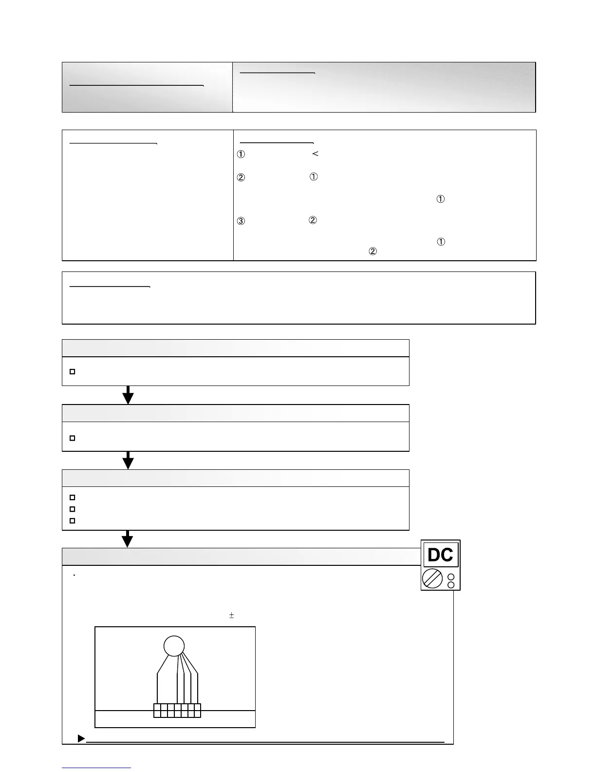
Check Point 4 : Check output voltage of Main PCB
If the voltage is not correct, replace Main PCB, and execute the check operation again.
BLACK
BLUE
RED
WHITE
YELLOW
CN243
1 2
3
4 5
6
1 2
3
4 5
6
FM
FAN MOTOR
Check outdoor unit circuit diagram and the voltage.
(Measure at Main PCB side connector 243)
>>1 pin(Red) - 4 pin(Black) DC250V ~ 400V
>>4 pin(Black) - 5 pin(White) DC15V 2V
7
7
02-48
 Loading...