- (02 - 21) -
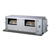
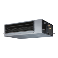
OUTDOOR UNIT
AOTG54LCTL
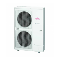
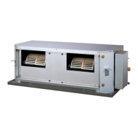
OUTDOOR UNIT
AOTG54LCTL
FUNCTION SETTING15.
FIELD SETTING SWITCHES15-1.
The positions of the switches on the outdoor unit control board are shown in the gure below.
FUNCTIONS
Caution
Discharge the static electricity from your body before setting up the push buttons.
Never touch the terminals or the patterns on the parts that are mounted on the board.
Terminal blocks
Push
buttons
LED lamps
Display lamp Function or operation method
(1) POWER / MODE Green
Lights on while power on.
Local setting in outdoor unit or error
code is displayed with blink.
(2) ERROR Red Blinks during error operation.
(3) PUMP DOWN (L1) Orange
Lights on during pump down
operation.
(4) LOW NOISE MODE
(L2,L3)
Orange
Lights on during “Low noise” mode
when local setting is activated.
(Lighting pattern of L2 and L3
indicates low noise level)
(5) PEAK CUT MODE
(L4,L5,L6)
Orange
Lights on during “Peak cut” mode
when local setting is activated.
(Lighting pattern of L4, L5 and L6
indicates peak cut level)
Button Function or operation method
SW1 MODE
To switch between “Local setting”
and “Error code display”.
SW2 SELECT
To switch between the individual
“Local settings” and the “Error code
displays”.
SW3 ENTER
To x between the individual “Local
settings” and the “Error code
displays”.
SW4 EXIT
To return to “Operation status
display”.
SW5
PUMP
DOWN
To start the pump down operation.
SW1
SW2
SW3 SW4 SW5
(1)
(2)
(3)
(4)
(5)
LED lamp
 Loading...