- 24 -
WALL MOUNTED
ASYG09-14LZCA
10. External input and output
With using external input and output functions, this product can be operated inter-connectedly with
an external device.
10-1. External input
With using external input function, some functions on this product can be controlled from an external
device.
• “Operation/Stop” mode or "Forced stop" mode can be selected with function setting of indoor unit.
• A twisted pair cable (22AWG) should be used. Maximum length of cable is 150 m.
• The wire connection should be separate from the power cable line.
Control input (Operation/Stop or Forced stop)
The air conditioner can be remotely operated by means of the following on-site work.
Unit operation is started at the following contents by adding the contact input of a commercial on/
off switch to a connector on the external control PCB and turning it on.
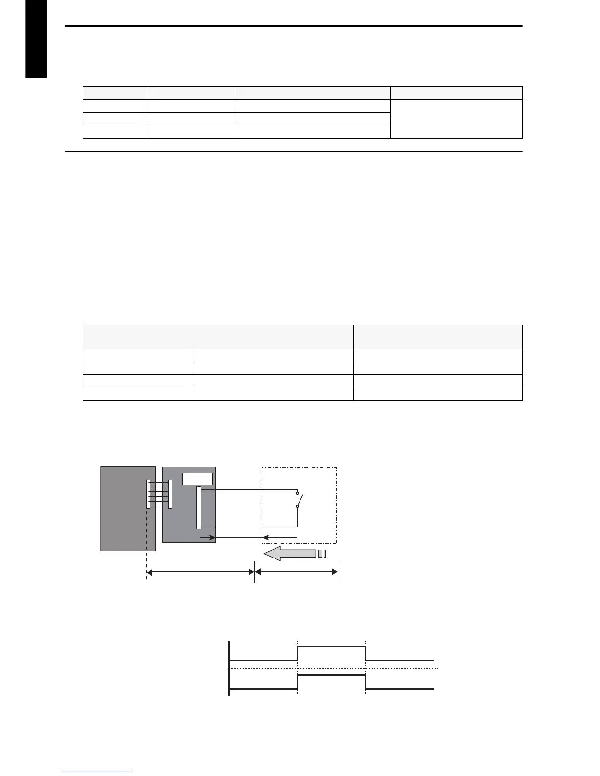
Circuit diagram example
When function setting is “Operation/Stop” mode
Connector Input Output Remarks
CNA01 Control input —
See external input/output
settings for details.
CNB01 — Operation status output
CNB02 — Error status output
Unit operation Initial setting after power is on
Starting mode other than initial
setting
Operation mode Auto changeover Mode at previous operation
Set temperature 24 °C Temperature at previous operation
Airflow mode AUTO Mode at previous operation
Air direction (swing) Standard air direction (swing: off) Air direction at previous operation
• Contact capacity: DC 24 V or more, 10
mA or more.
• *: Make the distance from the PCB to
the connected unit within 10 m.
• Use non-polar relays and switches.
 Loading...